background image

9

Biasing of the Power Tubes

Bias voltage applied to the grids of the power tubes in the output stage should be
checked from time to time (once a month) to keep these tubes operating at the optimum
operating point. A properly biased power tube will have a longer, happier life. 

To check the bias of the 6550C/KT88 tubes, place the amplifier in MUTE via the Input
Selector Switches (I), with the power on and the amplifier in OPERATE mode (STANDBY
LED Green; Power LED Red-for MUTE). Looking at the top surface of the amplifier, take
note of the power tube location and the bias LED below the surface of the chassis next to
each tube. Also note the printed line that leads to each power tube. At the opposite end
of this line is the bias adjustment for each power tube, again located below the chassis
surface. See reference diagrams for further clarification (Page 3).

If a bias LED is glowing red the tube is overbiased; if a bias LED is glowing green the
tube is underbiased, both conditions cause undue wear and/or are not optimal for the
tube. The LED should not be glowing at all for the proper operating bias. 

To properly bias the tubes is a simple procedure. For the power tubes on the left (V4 &
V5) insert the biasing driver into the slot head of the bias adjustment control and turn the
driver to adjust the control counterclockwise so the LED is green. Turn the adjustment
back clockwise until the LED begins to dim. At this point; through careful adjustment,
continue slowly turning the bias control, stopping the moment the LED goes out. No light
from the LED indicates a properly biased tube. For the most accurate biasing, the
biasing controls should always be rotated from the LED emitting gre e n
to the LED emitting no light, stopping immediately, as soon as the LED
emits no light.

Repeat procedure on the next tube until both tubes are properly

biased. Bias V9 & V10 in the same fashion as V4 & V5. You will need to go back and
forth a few times to set all LED’s to the “No Light” condition. For the first time adjustments
you will need to recheck and adjust the bias again after about 30 minutes of operation.

A cutaway of the tube 

top showing the location of 

the biasing controls below 

the tube top surface 

and the biasing driver.

Содержание Sonic Frontiers Power 1

Страница 1: ...Operating Manual for the Sonic Frontiers Power 1 Stereo Amplifier ...

Страница 2: ...ams 3 Installing the Tubes 5 Controls Functions and Connections 7 Biasing of the Power Tubes 9 Adjustment for Load Impedance 10 Care and Maintenance 12 Troubleshooting 13 Warranty 14 Specifications 15 This symbol is intended to alert the user to the presence of uninsulated dangerous voltage within the product s enclosure that may be of sufficient magnitude to constitute a risk of electric shock to...

Страница 3: ...on of the weight can make this awkward hint the back of the chassis is the heavy end Here is a chart listing what you will find in the box If after your inspection of the contents there is a discrepancy contact your dealer or Sonic Frontiers immediately Removing the Tube Cover To remove the cover loosen and remove the 4 screws installed from the bottom 2 per side Lift the cover straight up and awa...

Страница 4: ...g the Tubes and Biasing of the Power Tubes a must read for further clarification 4 Replace the tube cover as described in the Unpacking section If the tube cover is not used it is recommended that the tubes namely the 6550C KT88s are protected from settling dust in NON USE periods Dust settling on the tubes can cause heat impairment of the tubes 5 Connect your preamplifier s left and right balance...

Страница 5: ...icate placement for the 6550C KT88 power tubes A Holes on the Tube Top labeled A are LED indicators for the bias of the power tubes situated nearest B Holes labeled B are the location of the bias controls The bias controls adjust the bias of the tube which they are joined to by the lines Direction arrows around the controls indicate the rotation of the control to INCREASE the bias of the power tub...

Страница 6: ...el Input Selector Switches J Left and Right Channel Balanced XLR Inputs K Left and Right Channel Single Ended RCA Inverting Inputs L Left and Right Channel Single Ended RCA Non Inverting Inputs M Left and Right Channel Ground Posts N Left and Right Channel Loudspeaker Binding Posts This drawing is referred to as the Front Panel within the instructional text This drawing is referred to as the Rear ...

Страница 7: ...responding sockets also labeled on the amplifier s top surface See Reference Diagrams for further clarification Insert each tube in the corresponding socket Starting with the 9 pin small signal tubes the 6922s pay extra attention to the tube pins and socket holes for these tubes You will notice an open space where an imaginary tenth pin or hole would be This is for proper tube alignment Be sure pi...

Страница 8: ...e or the tube boxes to the corresponding markings printed on the tube top V4 V5 and V9 V10 and be sure the center pin key locator is in alignment with the slot in the center of the socket Again push down the tube rocking gently until it is firmly seated Note the locating center key and notch for proper alignment of tube and socket ...

Страница 9: ... not be biased up in this STANDBY mode E Power LED When this LED is off so is the amplifier When the LED is glowing red both channels are Muted controlled by the Input Selector Switches I When the LED is green the amplifier is receiving power and both inputs are selected the amplifier is ready for operation Green Power LED indicates ON Red Power LED indicates ON but in MUTE mode Green Red Orange i...

Страница 10: ...t is 180 out of phase relative to the original signal and correction for this configura Inverting Inputs tion is desired This input on the Power 1 does invert the phase of the output signal rela tive to the input signal Connections should be made left channel to left channel right channel to right L Left and Right Channel These inputs accept an input signal from a single ended output of a preamp o...

Страница 11: ... not optimal for the tube The LED should not be glowing at all for the proper operating bias To properly bias the tubes is a simple procedure For the power tubes on the left V4 V5 insert the biasing driver into the slot head of the bias adjustment control and turn the driver to adjust the control counterclockwise so the LED is green Turn the adjustment back clockwise until the LED begins to dim At...

Страница 12: ...he amplifier can be set to handle 4 or 8 ohm loads Some experimenting of this setting may be required for speakers which vary considerably in impedance across a frequency range To change the output setting have your Sonic Frontiers dealer follow these steps 1 Unplug all connections to the power amplifier namely the AC power supply cord and wait a minimum of 20 minutes for all power supplies to dis...

Страница 13: ...eplace the Transformer cover and screws tightening the front top 3 countersunk screws first then all the rest REAR OF THE AMPLIFIER Left Channel Shown REAR OF THE AMPLIFIER Left Channel Shown Adjustment for Speaker Load Impedance Cont d The final connections should resemble these diagrams ...

Страница 14: ... adequate operating temperatures How do I know when to replace the tubes If the tubes lack power to drive your speakers are hard to bias or won t hold bias it could be time for replacements Power tubes generally wear faster than small signal tubes but how much faster depends on how often you run your system If you need help determining these factors or sourcing replacement tubes contact your Sonic...

Страница 15: ...ower 1 will not be realized until and unless the unit receives a minimum of approximately 70 hours of signal break in time i e the Power 1 is on and outputting a signal Safety Instructions 1 Water and Moisture This product should not be used near water To prevent fire or shock hazard do not expose this product to rain or moisture 2 Heat This product should be situated away from heat sources such a...

Страница 16: ...e defect is due to the product being tampered with modified or repaired by anyone other than Sonic Frontiers Inc or an authorized Sonic Frontiers repair depot 3 Warranty does not cover normal maintenance 4 Sonic Frontiers Inc shall not be responsible in any way for consequential or indirect damages or liabilities resulting from the use and operation of the product covered herein or resulting from ...

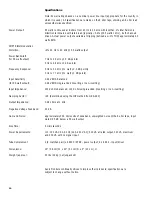
Страница 17: ...z to 77 kHz 1 watt 3 dB points Input Sensitivity 0 94V RMS balanced for 55 watt output 0 94V RMS single ended inverting or non inverting Input Impedance 200K ohms balanced 100K ohms single ended inverting or non inverting Damping Factor 35 determined using the IHF method from RS 490 Output Impedance 0 28 ohms at 1 kHz Negative Voltage Feedback 20 dB Hum and Noise approximately 300 microvolts of wi...

Отзывы: