Sonel LKZ-1500 Скачать руководство пользователя страница 1


Содержание LKZ-1500

Страница 1: ......

Страница 2: ......

Страница 3: ...USER MANUAL CABLES AND UNDERGROUND INFRASTRUCTURE LOCATOR LKZ 1500 LITE LKZ 1500 SONEL S A Wokulskiego 11 58 100 widnica Version 2 00 12 10 2021...

Страница 4: ...MANUAL 2 Locator LKZ 1500 is a modern high quality measuring device easy and safe to use Reading and us ing of this manual will help to avoid errors in measurements and prevent possible problems when...

Страница 5: ...ting the main parameters via Menu options 18 4 5 Operating modes of the receiver 21 4 6 Locating methods 23 4 6 1 Selection of operating frequency 23 4 6 2 Peak null and current direction modes 23 4 6...

Страница 6: ...ower supply 46 7 1 LKN 1500 power supply 46 7 2 LKO 1500 LITE LKO 1500 power supply 46 8 Possible faults and troubleshooting 47 8 1 LKO 1500 transmitter 47 8 2 LKO 1500 LITE LKO 1500 receiver 47 9 Mai...

Страница 7: ...tions Do not leave the transmitter connected to the object unattended Do not disconnect the wires from the object while the transmitter is operating Repairs may only be carried out by an authorized se...

Страница 8: ...f object as well as the location of insulation damage e g cables or pipelines Current output waveform for LKN 1500 is modified sine wave The transmitter can cooperate with any LKO receiver that has th...

Страница 9: ...ignal So the transmitter microprocessor produces control pulses Microprocessor also controls transmitter s conditioning by load to provide maximum power output The transmitter operation and status inf...

Страница 10: ...ls of internal accumulator charging process 18 Button for selecting the signal type double single 19 Double frequency selection indicators 20 Signal frequency selection button 21 Indicators of specifi...

Страница 11: ...tter Flashing green light Pulse normal operation of the transmitter Flashing red light at a frequency of 1 Hz Transmitter overheating Signal is not generated The generation is resumed only when the tr...

Страница 12: ...maximum survey current Otherwise current will leak off the ground through isolation capacitance and its level will decrease As a result it will reduce possible search range Fig 3 Connection the transm...

Страница 13: ...le power desired search time power supply source parameters and estimated search range Increase or decrease power output by pressing the buttons Indicator pos 5 Fig 2 shows power output value Indicato...

Страница 14: ...of communication lines or they carry voltage the survey current can be generated in the examined lines from induction coil or by inductive clamps 3 4 3 1 Internal transmitter inductor The transmitter...

Страница 15: ...signal to adjacent communication lines Select the clamps to match the diameter of the clamped wire see also section 13 2 NOTE Do not connect conductive clamps to live bare conductors Current resistan...

Страница 16: ...nd mode it locates utilities by re radiated broadcasting and telephone signals within the frequency band from 48 Hz to 14 kHz in the Radio modes it locates utilities by detecting induced broadcasting...

Страница 17: ...dphone jack Jack 6 3 mm 3 Battery compartment cover 4 Outlet for extra equipment A frame 5 Speaker A removable sun protective cover can be installed by securing its two Velcro straps by the receiv er...

Страница 18: ...LKZ 1500 LITE LKZ 1500 USER MANUAL 16 Fig 10 LKO 1500 receiver panel...

Страница 19: ...ing frequency selector button Button sets optimum signal gain in the TRACE or SENSOR channels depending on actual control area Measures the utility depth and intensity of current Switches on off the s...

Страница 20: ...ce turns on the firmware version number and the supply voltage If the voltage is below 5 8 V recharge the battery or replace the disposable batter ies The supply voltage is indicated with the battery...

Страница 21: ...off is set to 30 minutes by default The Type of sound submenu provides a selec tion of audio indication tones as follows o Tone a single frequency tone output The volume is be directly proportional to...

Страница 22: ...coordinates o PIN set the PIN code for GPS module pairing Fig 17 Menu GPS PC connection connection to computer GPS settings the settings of the receiver for pairing and operation with the GPS module...

Страница 23: ...ay of this mode is shown in Fig 21 To change the mode press and hold the button for 2 seconds Additionally with the COMPASS LINE option switched on the direction of the located cable rela tive to the...

Страница 24: ...exact value Red color approximate value no signal from LKN 1500 8 Input signal from the magnetic antenna in dB and also a scale of input signal relative level null scale when searching by null method...

Страница 25: ...sence of isolat ed connectors The generated signal achieves higher transmission into the adjacent utilities at the same time which may cause misleading determination of the direction of survey It is p...

Страница 26: ...ctions which facilitate high accuracy of tracing depending on the depth and density of utilities in the target zone Fig 23 shows the relationship between the signal level and antenna displacement from...

Страница 27: ...d provides maximum sensitivity of the Receiver As far as you move along the line the Receiver gain and the sound volume shall be adjusted de pending on the strength of the received signal Along the ro...

Страница 28: ...aph towards the utility Subse quent disposal of the antenna will result in smooth signal attenuation When you use the null method you should maintain the optimum gain level of the Receiver If the gain...

Страница 29: ...rength and polarity of signal at the SENSOR in put Locating with the COMPASS feature is shown in Fig 25 Moving along the target line try to arrange the Receiver relative to the utility so that the Uti...

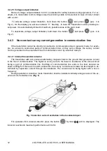
Страница 30: ...LKZ 1500 LITE LKZ 1500 USER MANUAL 28 Fig 25 Locating with Compass line...

Страница 31: ...er shall be connected directly to the target line for this technique The adjacent utili ties shall be galvanically separated from the target line in the point of connection see Fig 26 The target utili...

Страница 32: ...over the target utility axis as shown in Fig 28 The arrows on the Receiver body and antenna plain shall be perpendicular to the utility line axis Keep in mind that the errors of depth measurements may...

Страница 33: ...ground if they are located closer to the terrain surface However the target utility will always show the highest of all detected current values since current is independent from depth Current measurem...

Страница 34: ...surement by the 6dB method Fig 30 Depth measurement by the 6dB method Pinpoint the utility axis and store the readings of the input signal strength on the peak scale in dB Moving to the left and to th...

Страница 35: ...be identified easily When you use this technique please be sure that the current strength in the target line is much higher than in the adjacent utilities To achieve this connect the Transmitter dire...

Страница 36: ...ak bar graph is illuminated Move in zigzags by al ternating your direction in perpendicular every 1 to 5 m Fig 31 The signal strength will peak where the utility is Survey as explained in Section 4 6...

Страница 37: ...n the ends of the utility line If one of the ground contacts is missed the location will be difficult so the Transmitter shall be set on the maximum frequency to increase the currents via the capacity...

Страница 38: ...centreline is pointing towards that operator The other operator needs to walk along the opposite perimeter line while holding the locator and monitoring the variations on the bar graph Fig 33 The pea...

Страница 39: ...s DKI E or A frame Contact sensors of insulation control A frame and non contact sensors DKI E are used for loca tion Turn the Receiver into the Trace SENSOR mode The sensors shall be connected to the...

Страница 40: ...he Transmitter to generate the 1024 Hz double frequency signal and the Receiver to 1024 Hz operating frequency on the SENSOR input When the double frequency signal strength reaches a predefined thresh...

Страница 41: ...nates signal fluctuation error caused by different distances Measurements with this sensor however require the pins to be embedded into the soil that may be inconvenient in some cases Keep the insulat...

Страница 42: ...a and signal strength may drop case 1 or rise case 2 In the first case the dead short takes place when only the cable conductors are shorted In the second case the cable conductors are shorted to each...

Страница 43: ...not allow the use of the insula tion control the method of phase tracing may be applied It is optimum when the earth leakage im pedance can be up to 0 5 M The area of damaged insulation shall be dete...

Страница 44: ...ities 6 Data storage GPS navigation The Receiver stores the measured data in the non volatile memory including position from exter nal GPS module Connection to the external GPS module is wireless The...

Страница 45: ...on of the track number see sec 6 2 Fig 40 GPS settings display Fig 41 GPS PIN settings display The name and address of the GPS module quantity of detected satellites and defined coordi nates and time...

Страница 46: ...can be marked with dedicated tags e g to mark the areas of supposed insulation failure or utility branch To do so press the button and hold it pressed for 2 seconds The audible signal will be heard c...

Страница 47: ...i connection PC operating system re quirements are Windows XP SP2 SP3 Vista 7 8 10 To connect to a PC the PC must have a WiFi interface board installed or an external WiFi USB dongle connected The PC...

Страница 48: ...Receiver is powered by a battery pack The battery pack can be replaced with 5 disposable or rechargeable AA batteries The replacement batteries need to be installed in a dedicated box which is to be...

Страница 49: ...hor ized Sonel service Power supply unit failure Check power supply unit 8 2 LKO 1500 LITE LKO 1500 receiver Tab 6 Potential failures of LKO Fault Possible cause Remedies The Receiver fails to be swit...

Страница 50: ...rature from minus 50 to 70 relative humidity of 90 max at the temperature of 30 The impact of precipitation is not allowed Please note the following when storing the set disconnect all wires from the...

Страница 51: ...r accuracy is not rated at frequencies of 8928 and 32768 Hz Load conditioning range at maximum power output on frequencies Ohm 273 1024 Hz from 30 to 3000 8928 Hz from 30 to 2000 double frequency Outp...

Страница 52: ...Basic technical data Parameter Nominal frequency values during opera tion with the Transmitter and the fre quency specific Receiver sensitivity Frequency Hz Min sensi tivity m Frequency Hz Min sensi t...

Страница 53: ...n value mV 0 05 SENSOR input resistance M 1 Max input power W 2 Min continuous operating time at full battery pack charge in normal condi tions h 5 5 Rated for the Broad peak method The signal noise r...

Страница 54: ...e clip red 1 kV 20 A WAKRORE20K02 ground probe 23 cm WASONG23 battery charger Z16 transmitter WAZASZ16 battery charger Z17 receiver WAZASZ17 hanging strap WAPOZSZE6 bag L13 WAFUTL13 sun protecting cov...

Страница 55: ...NUAL 53 14 Service The manufacturer of the device provides all warranty and after warranty repairs SONEL S A Wokulskiego 11 58 100 widnica Poland tel 48 74 858 38 60 fax 48 74 858 38 09 E mail export...

Страница 56: ...imagers o luxmeters The Calibration Certificate is a document that presents a relation between the calibration standard of known accuracy and meter indications with associated measurement uncertainti...

Страница 57: ...LKZ 1500 LITE LKZ 1500 USER MANUAL 55 NOTES...

Страница 58: ...LKZ 1500 LITE LKZ 1500 USER MANUAL 56 NOTES...

Страница 59: ......

Страница 60: ......

Отзывы: