4
2.0 YOUR RECEIVER
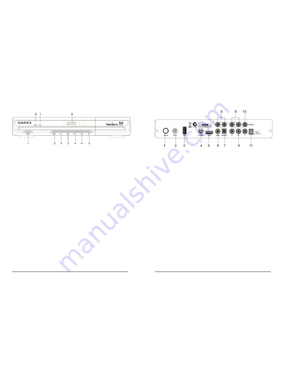
2.1 Front Panel
Figure 1
1.
POWER
Button
Turn the receiver on or standby.
2.
MENU
Button
Show the main menu or return to previous menu.
3.
CH-/CH+
Button
Moves the cursor up/down in Menu state. Change the current program to the previous/next
program in No-menu state.
4.
VOL-/VOL+
Button
Increases/decreases the volume levels in No-Menu state. Change the setting values in specific
Menu item.
5.
OK
Button
Executes the selected item in the menu screen, or confirm the input value.
6.
Power
indicator.
7.
Lock
indicator.
8.
Display (4-digi 7-segment)
4-digi displays channel information. In Standby mode the 7-segment displays local time.
5
2.2 Rear Panel
Figure 2
1. ANT
IN
RF Modulator (female part). If you have an additional antenna (cable or terrestrial) as well,
and you do not use a scart cable to connect the receiver to the TV, then your additional
antenna has to be connected here.
If you do use a scart cable to connect the receiver to your TV, the additional antenna can
be put directly into your TV.
2. TO
TV
Connect the receiver to your TV, using a coax cable.
3. USB
USB2.0 slot.
4. S-VIDEO
This jack connects to a TV or VCR that accepts S-Video input.
5. HDMI
HDMI output.
6. CVBS
AV Output.
7. OPTICAL
Use this optical output to connect your receiver to the input of your digital audio amplifier.
8. Y, Pb, Pr
Y/Pb/Pr output.
9. AUDIO Right and Left
These connectors give you the possibility to connect the audio signal to an external
amplifier, or the audio input of your TV.
10. COAXIAL
Connect with Dolby Digital decoder audio-visual equipment.
11. External DC power outlets.


