


3-22
Computer Group Literature Center Web Site
Functional Description
3
LAN A Control Register
Use the LAN A Control Register (LNACTRL) to control the on-card LAN
A controller. Bits written can also read back. Refer to
.
FRONT (Bit 6)
The BIOS uses this bit to route LAN A signals to either the front or the rear
connectors.
❏
Write a logic 0 to this bit to route LAN A signals to the front
connector.
❏
Write a logic 1 to this bit to route LAN A signals to the rear
connector.
The BIOS sets this bit according to CMOS setup.
ENABLE (Bit 7)
The BIOS uses this bit to enable LAN A.
❏
Write a logic 1 to this bit to disable LAN A.
❏
Write a logic 0 to enable LAN A so that the operating system and
applicaiton code can use it.
The BIOS sets this bit according to CMOS setup.
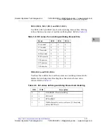
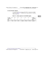
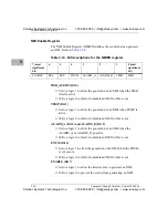
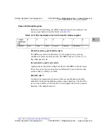
Table 3-19. Bit descriptions for the LAN A register
7 (most
significant
bit)
6
5
4
3
2
1
0 (least
significant
bit)
ENABLE
FRONT
RES
RES
RES
RES
RES
RES
Solution Systems Technologies Inc.
720-565-5995 | [email protected] | www.solusys.com
Solution Systems Technologies Inc.
720-565-5995 | [email protected] | www.solusys.com


