


3-18
Computer Group Literature Center Web Site
Functional Description
3
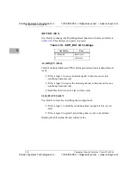
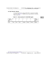
Alarm Enable Register
The Alarm Enable Register (ALEN) defines the events that generate an
alarm output. Refer to
.
SMB (Bit 0)
❏
Set to a logic 1 to allow the generation of an Alarm when the SMB
Alert is active.
❏
Write a logic 0 to this bit to disable an Alarm for this event
TEMP (Bit 1)
❏
Set to a logic 1 to allow the generation of an Alarm when TEMP is
active.
❏
Write a logic 0 to this bit to disable an Alarm for this event.
ALARM_A (Bit 3) and ALARM_B (Bit 2)
❏
Set to a logic 1 to allow the generation of an Alarm when the
ALARM_A or ALARM_B go active.
❏
Write a logic 0 to this bit to disable an Alarm for this event.
ENUM (Bit 4)
❏
Set to a logic 1 to allow the generation of an Alarm when the ENUM
event occurs.
❏
Write a logic 0 to this bit to disable an Alarm for this event.
ENABLE (Bit 7)
❏
Set to a logic 1 to allow the listed events to generate an Alarm.
❏
Write a logic 0 to prevent the events from generating an Alarm.
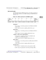
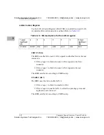
Table 3-16. Bit descriptions for the ALEN register
7 (most
significant
bit)
6
5
4
3
2
1
0 (least
significant
bit)
ENABLE
RES
RES
ENUM
ALARM_A
ALARM_B
TEMP
SMB
Solution Systems Technologies Inc.
720-565-5995 | [email protected] | www.solusys.com
Solution Systems Technologies Inc.
720-565-5995 | [email protected] | www.solusys.com


