ENGLISH
4
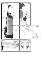
relief valve (
d
), the device must always be in an
upright position.
Attention: Keep the device away from your face!
To fill the tank with spraying agent, the pump must
be unscrewed. Push the pump handle (
c
) down
and turn it to the left (counterclockwise) until the
handle clicks into position.
Unscrew the pump by turning it counterclockwise.
Do not use any tools!
Fill the tank no further than to the mark “max. 9l” on
the side of the spray tank.
Overfilling the tank or spills can contaminate public
waterways, rain- and storm water channel and
must be avoided.
Wipe off spilled spray liquid without delay.
After filling, insert the pump again and refasten
firmly by turning the pump handle (
c)
clockwise to
prevent the spraying agent from escaping.
Refasten firmly until the pump handle clicks into
position.
8 Using the foam sprayer
8.1 Spraying
To pump, loosen the pump handle (
c
) by turning
out of the stop position. Pump the unit until the
operating pressure is reached in the spraying
agent tank. Excessive pressure escapes
automatically through the pressure relief valve (
d
).
Hold the spray wand with the hand valve.
Fig. 4:
To spray, depress the hand lever on the valve.
Release the hand valve lever to stop spraying.
The foam sprayer can also be carried by the pump
handle (
c
), if the pump handle is pressed down
completely, and it is turned to the right and clicked
into position.
8.2 Setting the foam consistency
Firm (dry) foam will adhere better and therefore
can act for a longer time, whereas liquid foam has
a higher concentration of spraying agent on the
area to be treated.
The foam adjustment unit (
g
) can be used to pre-
set consistency of the foam to be applied to match
the application.
x
Turn the setting wheel clockwise (in the
direction "dry") for firmer foam.
x
Turn the setting wheel counter-clockwise (in
the direction "wet") for more liquid foam.
The adjustment wheel area available for sensibly
usable levels of foam consistency differs by
spraying agent, spraying pressure and installed
spray nozzle.
8.3 Disposal of residual spray volume
Residual spray volumes of less than 200 ml
[6.8 oz] are no longer pumped effectively.
If you do not want to fill in any more spraying agent
and want to end spraying, collect and dispose of
the remaining amount according to the applicable
laws and provisions. Observe the information from
the spraying agent manufacturer.
At the end of the work, empty and clean the
sprayer according to chap. 9.2, wash face and
hands thoroughly and take off the work clothing.
Work clothing requires regular washing.
9 Maintenance, cleaning and storage
9.1 Greasing the sealing rings
Greasing the cap gasket
Fig. 5:
For proper sealing of the spraying agent tank, the
cap gasket (
l
) must be well greased with silicone
grease.
Greasing the pump piston sealing ring
If the pump is hard to operate, the sealing ring of
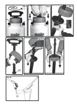
the pump piston (Fig. 9, pos.
m
) should be greased
with silicone grease or replaced if necessary.
Disassembly of the pump and greasing the
sealing ring:
Fig. 6: Ensure the sprayer is empty and not
pressurised. Place sprayer securely on level
ground. If the pump is completely screwed onto the
tank, loosen the pump with 1–2 turns.
Fig. 7: Firmly hold the pump handle with both
hands and push downwards until the pump
releases from the flange housing with an audible
click. Unscrew the blue flange housing from the
sprayer and remove the pump from the tank.
Fig. 8: Use a screwdriver to lever both black flange
semi-circles from the pump cylinder. The pump
piston can now be pulled from the pump cylinder.
Fig. 9: The sealing ring (
j
) can now be re-greased
with silicone grease or replaced if damaged.
Assembly:
Fig. 10: Place the blue flange housing correctly on
the pump piston.
Push the pump piston into the pump cylinder.
Push both black flange semi-circles onto the pump
cylinder until they lock with an audible click.
Fig. 11: Place the pump cylinder securely on level
ground. Line up the blue flange housing in the
exact position and firmly push the blue flange
housing down with both hands onto the pump
cylinder until the parts lock together with an audible
click.
Содержание CLEANLINE 309 FA
Страница 2: ...Fig 1 Fig 2 Fig 3 Fig 4 Fig 5 ...
Страница 3: ...Fig 2 Fig 9 Fig 6 Fig 7 Fig 8 Fig 10 Fig 11 Fig 12 ...


