


00-WTS-DB REV 1 11/2005
3
Modes of Operation Cont’d
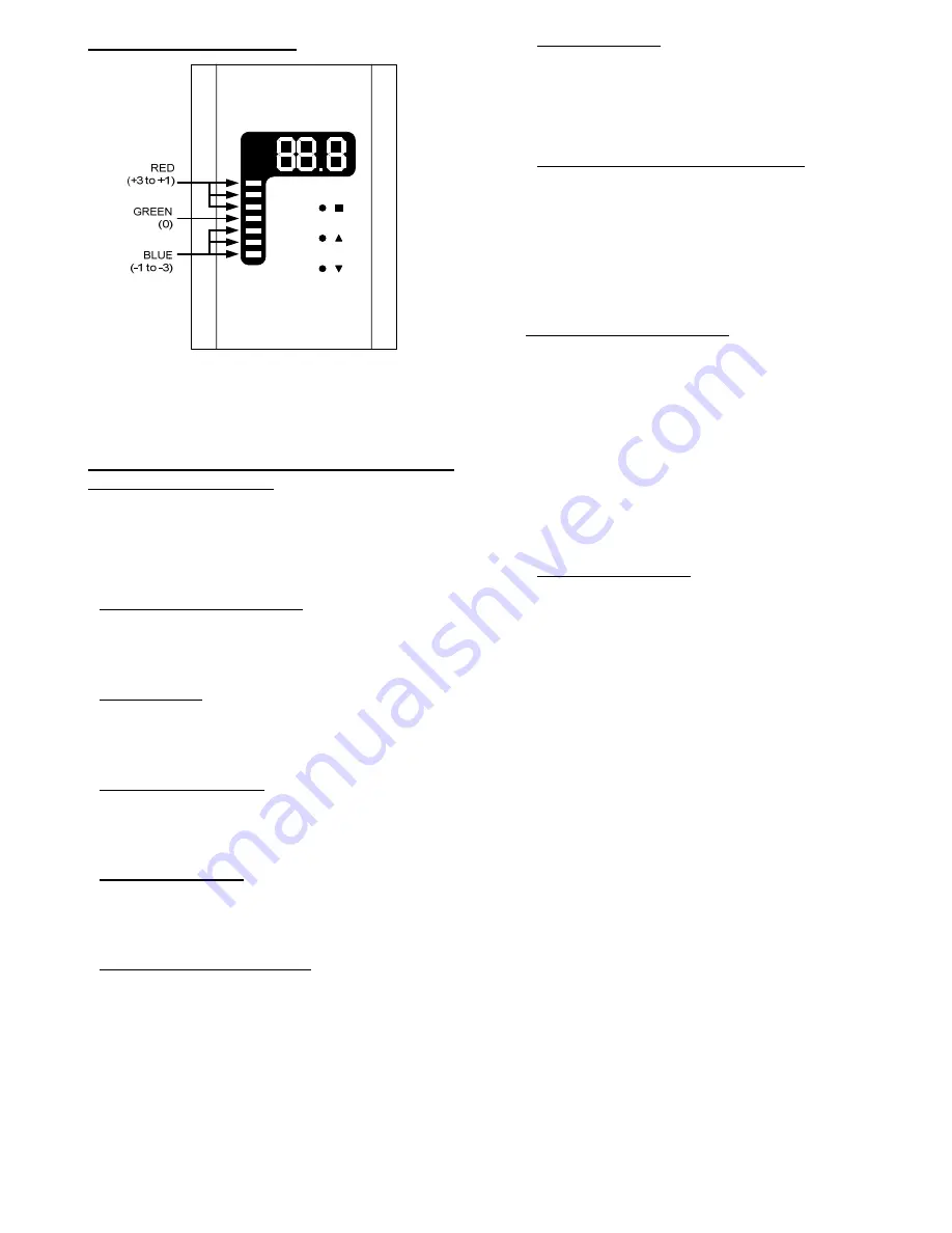
Figure 8
In Mode 2, when the highest red LED is lit, the Virtual Input #1 will be +3. Giving the
system an indication that the user would like the setpoint to be 3 degrees warmer than
current. Furthermore, if the green LED is lit, Virtual Input #1 would be set to a value of
zero (0). And when the lowest blue LED is lit, the Virtual Input #1 would be set to –3.
Configuring the WTS-DB operation with M2-
HH Commissioning Tool
The M2-HH commissioning tool is used to setup and configure
the 4 modes of operation for the WTS-DB. Please refer to the
M2-HH documentation for details of connecting and using the
M2-HH tool. All of the WTS-DB settings can be modified by
select F4 on the M2-HH tool.
Changing the Mode of Operation
To change the WTS-DB mode, select F4 on the M2-HH. The
first item on the list is the WTS-DB mode. Change the mode
number to whichever mode serves your application properly.
Disable Setpoint
In any of the 4 modes, the setpoint that is written to Virtual
Input #1 can be disabled by selecting the ZONE SET->VS1
setting to “N” by using the +/- key on the M2-HH.
Disable Light Level Sensor
To disable the built in light level sensor from writing to Virtual
Input #2, set the LITE SENS->VS2 setting to “N” by using the
+/- key on the M2-HH.
Disable Zone Overrides
To disable the user from triggering a zone override with the
WTS-DB, set the ZONE OVRD ENABLE to “N” by using the +/-
key on the M2-HH.
Calibrating the Zone Temperature
The WTS-DB temperature sensor can be calibrated by the M2-
HH if the sensor is not reading inside the desired accuracy
range. After selecting F4 for WTS-DB Settings, select the
DOWN arrow 4 times to get to the next page of the WTS-DB
settings. The first item in the list is SENSOR ADJUST. Select
OK and enter the desired amount of offset. Select OK when
Sensor Update Rate
The rate at which the zone temperature refreshes its value on
the WTS-DB can be adjusted between 1 and 256 seconds. In
the second page of the WTS-DB settings, select OK on the UP-
DATE RATE setting and enter the desired amount of seconds.
The default value is 5 seconds.
Changing the Min and Max Setpoint Values
WTS-DB Mode 1 uses a numerical setpoint which can have Mini-
mum and Maximum limits so that the user cannot change the
setpoint to an extreme value. By default the Minimum setpoint
value is 55 and Maximum is 85. Both of these values can be
change to a more desirable limit. On the second page of the
WTS-DB settings, select OK on either the MIN SETPOINT or
MAX SETPOINT and enter the desired values that apply to your
application.
Setpoint Adjust Operation
In both Mode 1 & 2, the user can adjust the zone setpoint. The
WTS-DB has 3 infrared emitter/receiver “buttons”. These are
not traditional mechanical buttons, rather they are electronic
components that require the user to cover a hole in the WTS-DB
housing which will give the same effect as pushing a mechanical
button. These electronic “buttons” are used to both change the
zone setpoint and set a zone override.
To change the setpoint in either Mode 1 or Mode 2, select either
the up or the down arrows to adjust the setpoint on the display
of the WTS-DB to the desired value and then select the enter
button which is the top button on the WTS-DB indicated by an
orange square.
Zone Override Operation
In all Modes of operation of the WTS-DB, the user can trigger a
zone override, typically used for after hours operation. The
duration of this override would be configured in the ICMS soft-
ware for Analog Input #1 and can be set for 1 to 255 minutes.
To trigger the zone override, the user should push the orange
square button. The display will display “OR=” for 1 second and
then the user can select either the up arrow to select the zone
override to ON which will be displayed on the WTS-DB. After
the override is selected to ON, select the orange square button
again to confirm the override. To view the current override
state, select the orange square button and the display will show
either OFF (zone not currently in override) or ON (zone cur-
rently in override).