Confidential & Proprietary 11/27
2.1.2.2
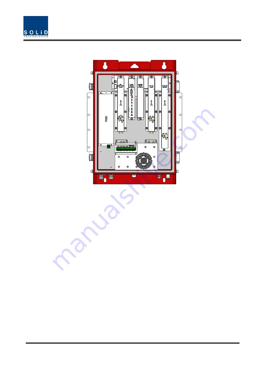
ROU inner look
Figure 4. Inside of Remote Unit
** In the HARU enclosure, not need to install R-Optic
Страница 1: ...Confidential Proprietary 1 27 ALLIANCE_PS2ROU User Manual ...
Страница 2: ...echnical support and or to establish a return authorization for defective units The serial numbers are located on the back of the unit as well as on the box in which they were delivered Additional support information may be obtained by accessing the SOLiD Tehcnology Inc website at www solid co kr or send email at sjkim solid co kr This manual is produced by Global Business Division Business Team P...
Страница 3: ...unction by unit 13 2 1 3 1 Public Safety 2W Remote Drive Unit PS2RDU 13 2 1 3 2 PS2ROU Power Supply 15 2 1 3 3 Remote Optic ROPTIC 16 2 1 3 4 Remote Central Processor Unit RCPU 17 2 1 3 5 Multiplexer 18 2 1 4 Bottom of PS2ROU 19 2 1 4 1 Functions 19 Section3 System Installation 20 3 1 PS2ROU Installation 20 3 1 1 Tools 20 3 1 2 PS2ROU Enclosure installation 21 3 1 3 PS2ROU Wall Mount Installation ...
Страница 4: ...er Look 13 Figure 10 R OPTIC Outer Look 17 Figure 11 AC DC RPSU Outer Look 17 Figure 12 Multiplexer Outer Look 18 Figure 14 The Bottom Look of PS2ROU 19 Figure 17 How to install ROU 21 Figure 18 Dimension used to install PS2ROU on the WALL 22 Figure 23 Location of Optical Connector 24 Figure 26 Location of ALM IN OUT Connector 25 Figure 29 Location of each modules in the PS2ROU 25 ...
Страница 5: ... and continuously emit RF energy Avoid prolonged exposure to the antennas SOLiD recommends maintaining a 500 cm minimum clearance from the antenna while the system is operating Antennas must be installed in accordance with FCC 27 50 and SRSP 517 With 17dBi gain antennas the height of the antenna above average terrain HAAT must not exceed 557 40m For different gain antennas refer to the relevant ru...
Страница 6: ...em All components connected to this device must operate in the frequency range of this device Only 50 ohm rated antennas cables and passive components operating from 150 3 GHz shall be used with this device The head end unit must always be connected to the Base Station using a direct cabled connection This system has not been approved for use with a wireless connection via server antenna to the ba...
Страница 7: ...prohibited Home personal use are prohibited UL CUL This equipment complies with UL and CUL 1950 1 Standard for safety for information technology equipment including electrical business equipment FDA CDRH This equipment uses a Class 1 LASER according to FDA CDRH Rules This product conforms to all applicable standards of 21 CFR Chapter 1 Subchaper J Part 1040 IC Booster warning label message should ...
Страница 8: ...sponding PS2RDU band combined with UDCU PAU and Cavity Filter and then radiated to the antenna port When receiving RX signals through the antenna port this unit filters out of band signals in a corresponding PS2RDU and sends the results to R OPTIC to make electronic optical conversion of them After converted the signals are sent to a upper device of ODU PS2ROU can be equipped with up to three PS2R...
Страница 9: ...c Remark PS2ROU The rated mean output Power per band 700PS_FN 33dBm 800PS 33dBm VHF UHF 24dBm 900I_PA 33dBm The nominal downlink bandwidth 700PS_FN 17MHz FCC 758 775MHz ISED 758 775MHz 800PS 10MHz FCC 851 861MHz ISED 851 861MHz VHF 38MHz FCC 150 174MHz ISED 138 174MHz UHF 132MHz FCC 406 1 512MHz ...
Страница 10: ... 940MHz ISED 929 930MHz 932 932 5MHz 932 5 935MHz 935 940MHz The nominal Uplink bandwidth 700PS_FN 17MHz 788 805MHz 800PS 10MHz 806 816MHz VHF 80MHz 136 216MHz UHF 132MHz 380 512MHz 900I_PA 6MHz 896 902MHz 2 1 2Block Diagram of PS2ROU 2 1 2 1 PS2ROU block diagram Figure 3 PS2ROU Block diagram ...
Страница 11: ...Confidential Proprietary 11 27 2 1 2 2 ROU inner look Figure 4 Inside of Remote Unit In the HARU enclosure not need to install R Optic ...
Страница 12: ...s and vise versa Compensate optical loss Communicate with legacy BIU or iBIU OEU though the FSK modem 5dBo optical link between ODU OM4 and ROU 10dBo optical link between ODU OM1 and ROU Fiber Connector SC APC Connector Fiber Type Single Mode Fiber Optical Wavelength 1310 1550 WDM RCPU Remote Central Processor Unit Controls signal of each unit Monitors legacy BIU or iBIU ODU OEU through the FSK mo...
Страница 13: ...to Remote Optic In the unit there is ATT to adjust gain PS2RDU consist of UDCU PAU like below figure and all modules are merged with one package Figure 5 PS2RDU Outer Look PS2RDU devices are varied for each frequency band including the following No Unit Naming Description Frequency Bandwidth TX RX 1 PS2RDU_E_VHF_UHF Dual band VHF FCC 150 174MHz ISED 138 174MHz UHF FCC 406 1 512MHz ISED 406 1 430MH...
Страница 14: ...Confidential Proprietary 14 27 ISED 758 775MHz 800PS FCC 851 861MHz ISED 851 861MHz 3 PS2RDU_90I_PA Single band FCC 929 930MHz 935 940MHz ISED 929 930MHz 932 932 5MHz 932 5 935MHz 935 940MHz 896 902MHz ...
Страница 15: ... and only a single type of power cable is provided The pin discription of AC port is as below Pay attention to the correct polarity Check if the connection is the same as one seen in the table above and make sure to turn the power ON The figure below is the AC power cable that comes with the unit Figure 4 5 AC Power Supply ...
Страница 16: ...ion is the same as one seen in the table above and make sure trn the power ON The figure below is the DC power cable included in the package Figure 4 6 DC Power Supply 2 1 3 3 Remote Optic ROPTIC Remote Optic converts optical signals into RF signals and performs vice versa It also has internal ATT for optical compensation to compensate for optical cable loss It provides two path in pairs TX RX to ...
Страница 17: ...ront of the module it has LED indicator to show system status letting you check any abnormalities at a time At the same front it also has communication LED Indicators to show communication status with upper devices THROUGHgh Local port the unit enables you to check and control device status throughgh PC and laptop It provides three interface port with ARUs to communicate with these It also provide...
Страница 18: ...lled combine unit CU works as a module to combine or distribute multiple signals into one or two antennas This device has a port to combine multiple signals You need to connect input and output ports of RDU throughgh a corresponding port Figure 8 Multiplexer Outer Look ...
Страница 19: ...tical Port 1EA SC APC Waterproof Optiacl Input port 2 Power Port 1EA The cable is directly inserted in port hall 3 VHF UHF Port 2EA VHF UHF Tx port and VHF UHF Rx Port 4 Antenna port 1EA DIN to N type 5 External Alarm Port 2EA 6 External alarm has been located in bottom 6 external alarm could set as input and output 6 LUG 1EA Ground ...
Страница 20: ... method and Optic Cabling and RF Interface Furthermore by showing power consumption of modules to be installed in each unit it presents Power Cabling budget in a simple way Then it describes the quantity of components of modules to be installed in each unit and expansion method 3 1 1Tools Tools needed for installation is table below No Tools Q ty Specification Remark 1 1 3Ø Length is more than 20m...
Страница 21: ...he unit has the structure of one Body enclosure It satisfies water proof and quake proof standards equivalent of UL Type4X The way to install for both PS2ROU has same method Basically PS2ROU is attached with wall mountable bracket PS2ROU can be mounted into either of wall or on a pole Figure 10 How to install ROU ...
Страница 22: ...Enclosure when is delivered It doesn t need to remove bracket to install enclosure simply after installing 4 of M12 mounting bolts secure 4 mounting bolts tightly First install 2 of M12 mounting bolts roughly half way on the enclosure and install enclosure over the bolts and secure tightly Second install 2 of M12 mounting bolts under the enclosure and secure tightly ...
Страница 23: ...enna connection 1EA optional Power Cable The cable is directly inserted in port hall 1EA PS2ROU PS2RDU Max 3RDUs in the one enclosure Max 3EA Basically the common part of PS2ROU should have an enclosure and it is equipped with RCPU to inquire and control state of each module R_OPTIC to make both of electronic optical and optical electronic conversions RPSU to supply power for PS2ROU It should have...
Страница 24: ...ted at the bottom of Remote Unit enclosure fixed Optical Cable can be connected by using connectors The specification of compression Optic Connector is like below The way to install the Optical cable comply with below procedures The procedures are Figure 12 Location of Optical Connector ...
Страница 25: ...ng of PS2RDU PS2ROU has slots to enable up to four PS2RDU modules to be mounted in it You can mount a PS2RDU into designated slot surely and should install each PS2RDU into its designated location as shown in the installation diagram on the door of enclosure It is not possible to provide services with a PS2RDU module alone you need to connect PS2RDU cavity duplexer antenna port with CU s designate...
Страница 26: ... operated with a minimum distance of 210 cm between the radiator and your body This transmitter must not be co located or operating in conjunction with any other antenna or transmitter RF exposure will be addressed at time of installation and the use of higher gain antennas require larger separation distances Max antenna gain DL 17 dBi RSS GEN SEC 7 1 2 TRANSMITTERS Under Industry Canada regulatio...
Страница 27: ...r chaque type d antenne Les types d antenne non inclus dans cette liste ou dont le gain est supérieur au gain maximal indiqué sont strictement interdits pour l exploitation de l émetteur RF RADIATION EXPOSURE This equipment complies with RF radiation exposure limits set forth for an uncontrolled environment This equipment should be installed and operated with a minimum distance of 210cm between th...