


4.2
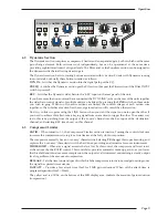
Dynamics Section
The Dynamics section comprises a compressor/limiter and an expander/gate, both of which use the same
gain change element. Both sections work independently, but can be operational at the same time,
providing sophisticated control of signal levels. The Filter and/or the Equaliser section can be assigned to
the dynamics side chain allowing de-essing etc.
The Dynamics section has two routing buttons associated with it. Section 5 deals with Dynamics routing
in more detail, but briefly these button function as follows:
DYN IN
– Switches the Dynamics section into the signal path pre the EQ.
PRE EQ
– Switches the Dynamics section pre the EQ section (but post the Filter section if the Filter INPUT
switch is pressed).
KEY
– Switches the Dynamics side chain to the ‘KEY’ input on the rear panel of the unit.
If you have more than one unit and have connected the ‘DYN LINK’ jacks on the rear of the units together
the side chain control signals of multiple units can be linked by pressing the
LINK
switch on those units
you wish to gang. When two Dynamics sections are linked, the control voltages of each section sum
together, so that whichever section has the most gain reduction will control the other section.
Don’t try to link two gates using the LINK button when you want the signal on one to open the other. If
you need to achieve this effect, take a keying signal from one section to trigger the other. The easiest way
to do this is by patching from the output of the ‘source’ channel into the Key input of the ‘destination’
channel, and selecting KEY (see above) on this channel.
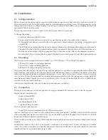
4.3
Compressor/Limiter
RATIO
– When turned to 1:1, the Compressor/Limiter section is inactive. Turning the control clockwise
increases the compression ratio to give a true limiter at the fully clockwise position.
The compressor normally has an ‘over-easy’ characteristic. Selecting
PK
changes this to peak sensing, and
replaces the ’over–easy’ characteristic with a hard knee, providing an alternative for some instruments.
THRESHOLD
– Whenever a signal exceeds the level set by this control, the compressor will start to act
at the ratio set by the RATIO control. This control also provides automatic make-up gain, so as you lower
the threshold and introduce more compression, the output level is increased, maintaining a steady output
level regardless of the amount of compression.
RELEASE
– Sets the time constant (speed) with which the compressor returns to normal gain settings once
the signal has passed its maximum.
FAST ATT –
Provides a fast attack time (3mS for 20dB gain reduction). When off the attack time is
program dependent (3mS – 30mS).
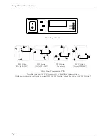
The yellow and red LEDs, on the bottom of the LED display area, indicate the amount of gain reduction
(compression).
Operation
Page 9
RELEASE
4
EXP
HOLD
0
THRESHOLD
+10
0
3
0
COMPRESSOR
+10
1
20
14
10
6
3
RELEASE
1
4
0
-20
RATIO
1
∞
DYN
IN
KEY
LINK
PRE
EQ
PK
FAST
ATT
DYNAMICS
FAST
ATT
GATE
RANGE
0
40
THRESHOLD
4
Содержание XLogic Super Analogue
Страница 1: ...Super Analogue Channel Owner s Manual ...
Страница 2: ......
Страница 29: ...Notes Appendix Page 25 ...
Страница 30: ...XLogic Channel Owner s Manual Page 26 ...


