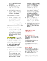
security strut. Lower the cutter so
the rear of the cutter is on the
ground or floor surface. Some
customers use a 10+” tree and tilt
the cutter back fully and rest it
against the tree while installing the
blades. Make sure to apply the skid
steer brakes and/or place tire chocks
to control any movement.
Insert the blade bolt up through the
hole in the blade and the blade holder
and insert the Lockwasher and nut
through the access hole in the deck.
Hand-tighten first, followed by
applying a torque of 650 lb-ft. with a
torque wrench.
Carefully remove the 4”x 4” post.
Blade Holder Removal &
Installation
Removal:
Tilt the skids steer’s tool cylinder all
the way back to place the attachment
in a near vertical position. Secure the
front of the cutter with an overhead
hoist or prop a 4” x 4” under the front
or lean the cutter head against a large
tree to support it in the raised position.
Be cautious
during the following step. The blade
cutter could fall resulting in Minor
or Serious Injury. Stand to the side.
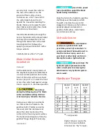
Remove cap, cotter pin and castle
nut that secure the holder to the
gearbox shaft. If holder cannot be
removed, start the skid steer and
place the cutter level and jar the
cutter on the floor or ground surface.
The holder should separate from the
gearbox flange. Repeat if necessary.
Installation:
Use a hoist, power
jack or forklift to support the blade
holder during installation
Align the hole in the holder to gearbox
shaft fully seat the holder on shaft.
Tap with a hammer to assure full
engagement. Make sure the holder is
properly aligned and seated on
gearbox shaft splines. Install castle
nut, cotter pin and cap.
Hydraulic System
A small stream
of oil from a pinhole leak could
penetrate your skin if contacted. To
avoid an accident that could result in
Death or Serious Injury, never use
your hand or other body parts in an
attempt to locate a hydraulic leak.
Always release the
hydraulic system pressure from the
cutter circuit prior to removing the
attachment or any hydraulic system
service work.
Hardware Torque
Grade 2
Grade 5
Grade 8
lb-ft
lb-ft
lb-ft
¼”
66*
8
12
5/16”
10
17
20
3/8”
20
30
45
½”
45
75
110
¾”
160
260
380
7/8”
190
400
600
1”
-
580
900
*
= inch pounds
Higher torques require the
use of a torque multiplier.
All values are “dry” torques.


