background image

Installation


and


Operation


Manual


(Rev


A)


PVI


50

100KW


Series


Inverters


DOCR

070233


Page


43


of


92


6.7


Stopping


and


Starting


the


Inverter


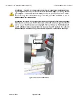
WARNING:


Before


conducting


any


maintenance


or


service


on


the


PV


System


the


inverter


disconnect


switches


must


be


set


to


the


“OFF”


position


and


the


absence


of


voltage


must


be


verified


by


qualified


personnel.


Do


not


rely


on


HMI


functions


to


stop


the


inverter


as


a


reset


might


cause


the


inverter


to


start


unexpectedly.


Quick


Stop


and


Start


The


Inverter


can


be


temporarily


stopped


so


that


it


ceases


to


export


power


to


the


grid.


Hold


down


the


ESCAPE


button


for


two


seconds


to


temporarily


stop


the


inverter


if


it


is


running.


Likewise,


hold


down


the


ESCAPE


button


for


two


seconds


to


initiate


inverter


starting


if


it


is


stopped.


Alternatively,


the


inverter


can


be


started


and


temporarily


stopped


through


the


menu.


1.


From


the


Main


Menu


select


the


Set


Inverter


function


and


then


press


the


ENTER


button.


2.


The


Power


Stopped


status


will


be


displayed,


indicating


the


current


status.


3.


Press


the


ENTER


button.


The


display


prompt


will


change


to


Power


Stop


and


the


setting


can


be


modified.


Press


the


DOWN


button


to


change


the


setting


to


Yes

.


4.


Press


the


ENTER


button


to


accept


the


setting.


The


inverter


will


shut


down.


NOTE:


To


start


the


inverter,


change


the


Power


Stop


setting


in


step


3


to


No


instead


of


Yes

.


Содержание PVI 100KW

Страница 1: ...Installation and Operation Manual Rev A PVI 50 100KW Series Inverters DOCR 070233 PVI 50KW PVI 60KW PVI 75KW PVI 85KW PVI 100KW INSTALLATION AND OPERATION MANUAL 2013 Solectria Renewables LLC ...

Страница 2: ...Series Inverters DOCR 070233 Page 2 of 92 IMPORTANT REGISTRATION AND WARRANTY INFORMATION For warranty to become active this inverter must be registered To activate warranty and register inverter please visit the link below www solectria com registration ...

Страница 3: ... during installation and maintenance of the inverter To reduce the risk of electrical shock and to ensure the safe installation and operation of the inverter the following safety symbols are used to indicate dangerous conditions and important safety instructions WARNING Use extreme caution when performing this task This indicates a fact or feature very important for the safety of the user and or w...

Страница 4: ... risk of injury to persons The enclosure includes a lockable handle and comes with a key Keep the key in a safe location in case access to the cabinet is needed A replacement key can be purchased from Solectria Renewables SAVE THESE INSTRUCTIONS PRESCRIPTIONS DE SECURITE IMPORTANTES Tous les travaux d installation électrique doivent être exécutés en conformité aux normes électriques locales ainsi ...

Страница 5: ...Cable Entry 24 Standard DC Disconnect Switch 27 Fused DC Subcombiner 27 DC Breaker Subcombiner 28 4 7 DC Ground Fault Detection and Interruption 28 4 8 Lightning and Surge Protection 30 4 9 Remote Shutdown and Revenue Grade Meter Terminals 30 5 Commissioning the Inverter 32 5 1 Turning on the Inverter 32 5 2 Operation 33 5 3 Turning Off the Inverter 33 6 Inverter Control and Communications in the ...

Страница 6: ...aying Error Logs 68 6 24 Clearing Error Counts or the Log 70 6 25 HMI Menu Structure 72 7 Troubleshooting and Maintenance 73 7 1 Inverter Messages 73 7 2 Troubleshooting 75 7 3 Preventative Maintenance 76 7 4 Intake Louver Vent Cleaning 77 7 5 Opening Main Enclosure DC Disconnect Switch and AC Disconnect Switch 77 7 6 Fuse replacements 79 7 7 Warranty Policy 80 7 8 Return Material Authorization Po...

Страница 7: ...hase commercial industrial institutional or electrical utility facility s electrical system which is connected to the electrical grid If the PV system and inverter are providing the same amount of electrical power that the facility is using then no power is taken from or fed into the utility grid If the facility is using more power than the PV system is providing then the utility grid provides the...

Страница 8: ...ies Inverters DOCR 070233 Page 8 of 92 Figure 1 2 PVI Inverter Front View Figure 1 3 PVI Inverter Rear View DC disconnect switch Nameplate Exhaust Air Output Cooling Air Intake AC Disconnect LCD Display Keypad LED Indicators Communications or SolrenView AIR ...

Страница 9: ...n Criteria for Device Mounting Because the power electronics are within the rainproof enclosure the inverter can be mounted outdoors The longest life for the inverter can be achieved by mounting the unit in a clean dry and cool location For optimal electrical system efficiency use the shortest possible AC and DC cables and use the maximum allowable cable size Avoid installation in close proximity ...

Страница 10: ...rature at the intake rises above 130o F 55o C The cooling air exhausts at the rear and bottom of the enclosure Nothing should block the 4 inch clear space under the enclosure between the mounting feet A minimum distance of 8 inches 200mm must be clear behind the inverter for rear cooling air exhaust 12 inches 300mm is recommended A minimum distance of 12 inches 300mm must be clear above the invert...

Страница 11: ...en though it is bolted onto a rugged oversized pallet for delivery the inverter may have been damaged during shipping by poor handling trucking or transfer station activity Please inspect the inverter thoroughly after it is delivered If any damage is seen immediately notify the shipping company to make a claim If there is any question about potential shipping damage contact Solectria Renewables Ph...

Страница 12: ...wing DOCR 070190 for the minimum recommended chain length to prevent damage to the inverter 3 3 Mounting Details WARNING Do not install the inverter on or over combustible surfaces or materials The inverter includes mounting feet with four holes sized for diameter hardware Refer to the diagram below and the customer interface drawing DOCR 070190 for detailed mounting dimensions It is recommended t...

Страница 13: ...Installation and Operation Manual Rev A PVI 50 100KW Series Inverters DOCR 070233 Page 13 of 92 Fig 3 3 Mounting Hole Diagram View from top of Inverter ...

Страница 14: ...on thoroughly clean the conductor just prior to making the electrical connection and use an oxide inhibitor to prevent the formation of aluminum oxide NOTE Grounding and power wiring terminals are rated to 167 F 75ᵒC NOTE When conduit hubs are used for DC and AC cable entry in an outdoor or wet location rain tight or wet location hubs that comply with the requirements in the Standard For Fittings ...

Страница 15: ... AC EGC o Ground Bar For DC EGC connection s AC Disconnect Switch o Ground Lug 400A AC disconnect switch only For AC GEC in systems with separate DC and AC GEC s o Ground Bar For AC EGC connection s Depending on the grounding system configuration the AC ground bar may also serve as the connection point for the AC GEC The DC and AC grounding connection points are internally bonded within the invert...

Страница 16: ...connect Switch Shown Fig 4 1b AC Ground Connection 400A 400A Unfused AC Disconnect Switch Shown AC Disconnect Switch Type AC Ground Connection Max Number of Connections Conductor Range Torque 200A Ground Bar 2 6 AWG 1 0 AWG 40 in lbs 400A Ground Bar 2 4 AWG 1 0 AWG 40 in lbs Ground Lug 1 2 AWG 250 kcmil 275 in lbs See Tables 4 3 4 4 to determine the AC disconnect switch type by inverter model Tabl...

Страница 17: ...round Connection 600A DC Disconnect Switch w DC Breakers Shown DC Disconnect Switch Type DC Ground Connection Max Number of Connections Conductor Range Torque 400A Ground Bar 4 14 1 0 AWG 40 in lbs Ground Lug 1 6AWG 250kcmil 275 in lbs 600A Ground Bar 5 14 6 AWG 40 in lbs Ground Lug 1 6AWG 250kcmil 275 in lbs See Table 4 6 to determine the DC disconnect switch type by inverter model Table 4 2 DC G...

Страница 18: ...e rotation of the grid connections to the inverter must follow the L1 A L2 B and L3 C clockwise order NOTE When a fused AC disconnect switch is not provided overcurrent protection of AC power output cables shall be provided by others according to local state and national code requirements The PVI 50 100KW models come with either a standard AC disconnect switch without fuses or optional fused AC di...

Страница 19: ... to determine which disconnect switch your inverter uses and then refer to the customer interface drawing DOCR 070190 for AC cable entry locations AC Voltage Drop AC voltage drop should be minimized to avoid nuisance tripping resulting from increased AC voltage seen at the inverter s output terminals as the inverter feeds current into the grid Minimizing AC voltage drop also results in higher syst...

Страница 20: ...1 0AWG 300kcmil 500 in lbs PVI 100KW 208V 1 500kcmil 750kcmil 500 in lbs 400A 2 2 0AWG 300kcmil 500 in lbs 240V PVI 50KW 240V 1 1 0AWG 250kcmil 275 in lbs 200A PVI 60KW 240V 1 3 0AWG 250kcmil 275 in lbs 200A PVI 75KW 240V 1 4 0AWG 750kcmil 500 in lbs 400A 2 1 0AWG 300kcmil 500 in lbs PVI 85KW 240V 1 300kcmil 750kcmil 500 in lbs 400A 2 1 0AWG 300kcmil 500 in lbs PVI 100KW 240V 1 350kcmil 750kcmil 5...

Страница 21: ... 500 in lbs 400A 2 1 0AWG 300kcmil 500 in lbs PVI 100KW 208V 350A 1 500kcmil 750kcmil 500 in lbs 400A 2 2 0AWG 300kcmil 500 in lbs 240 PVI 50KW 240V 150A 1 1 0AWG 250kcmil 275 in lbs 200A PVI 60KW 240V 200A 1 3 0AWG 250kcmil 275 in lbs 200A PVI 75KW 240V 225A 1 4 0AWG 750kcmil 500 in lbs 400A PVI 85KW 240V 300A 1 300kcmil 750kcmil 500 in lbs 400A 2 1 0AWG 300kcmil 500 in lbs PVI 100KW 240V 300A 1 ...

Страница 22: ...conductor is connected to the inverter currents may flow on the neutral due to site specific characteristics of the electric service feeding the project site such as voltage imbalance and voltage harmonics This neutral current may increase the inverter s operating temperature reduce inverter efficiency and shorten the inverter s life If a neutral is connected at the inverter it is the customer s r...

Страница 23: ... Sizes Torques 4 5 AC Ground Fault Detection The PVI series of inverters are not equipped with AC ground fault protection When AC ground fault protection is used on the onsite electrical service determine if the ground fault device is listed to be backfed The inverter AC output should be connected on the supply side of the device unless the device is specifically listed for a backfeed application ...

Страница 24: ...Optional string subcombiners are offered See Tables 4 8 4 9 and inverter spec sheet link provided in Section 9 1 for more information on DC disconnect switch integrated overcurrent protection options fusing or breakers amperage and quantity DC Cable Entry The DC cable entry location depends on the DC disconnect switch current rating and orientation side facing or forward facing Use Table 4 7 to de...

Страница 25: ... with 6 70 100A Fuses Subcombiner with 4 110A 200A Fuses Figure 4 6a DC Power Connection Locations 1 of 2 Grounded Conductor Connection Grounded Conductor Connection Grounded Conductor Connection Grounded Conductor Connection Ungrounded Conductor Connection Ungrounded Conductor Connections Ungrounded Conductor Connections Ungrounded Conductor Connections ...

Страница 26: ...ombiner with 3 110A 200A Breakers Subcombiner with 2 225A 300A Breakers Figure 4 6b DC Power Connection Locations 2 of 2 Grounded Conductor Connection Grounded Conductor Connection Grounded Conductor Connection Grounded Conductor Connection Ungrounded Conductor Connections Ungrounded Conductor Connections Ungrounded Conductor Connections Ungrounded Conductor Connections ...

Страница 27: ...il 275 in lbs 500 in lbs 400A PVI 60KW PVI 75KW PVI 85KW 2 1 0AWG 350kcmil 275 in lbs 375 in lbs 600A PVI 100KW Table 4 7 DC Disconnect Switch Conductor Size and Torques Fused DC Subcombiner The table below includes requirements for the DC conductor size the number of terminals available and proper terminal torque for the fused DC subcombiner options on the PVI 50 100KW NOTE The torque is differen...

Страница 28: ...DC Ground Fault Detection and Interruption The inverter is equipped with an automatic DC Ground Fault Detection and Interruption GFDI circuit When a single ground fault exceeding the ground fault fuse pickup value is present in the PV array or in the DC wiring to the inverter the DC GDFI fuse will blow and a ground fault will be signaled by means of a yellow LED and a message on the front LCD disp...

Страница 29: ...tions may cause the grounded conductor to rise to potentially unsafe voltage levels WARNING Even when the DC disconnect switch is in the off position the ungrounded DC conductor leading up to the DC disconnect switch will remain energized on the PV side as long as the PV modules are in daylight The inverter side of the DC disconnect switch will also remain energized after the disconnect switch has...

Страница 30: ...hin the SPD A red indicator flag will mark that an insert requires replacement The SPD s can are installed inside the DC disconnect switch Added protection and proper grounding provisions will help protect against utility surges and surges created by indirect lightning strikes In some instances surge and lightning can damage the equipment Please review the warranty section for details 4 9 Remote S...

Страница 31: ...emote Shutdown Wiring The PVI 50 100KW inverters feature a remote shutdown input to allow for advanced remote command and control systems The input required is an isolated 24VDC signal that is wired to the terminal blocks on the left panel of the inverter by the installer Once the signal is activated the inverter will slowly ramp down power and then disconnect from the grid The inverter will not r...

Страница 32: ...ative PV connections NOTE Verify clockwise AC phase rotation for L1 L2 L3 using a phase rotation meter 5 1 Turning on the Inverter WARNING The inverter may only be turned on by trained and qualified personnel only Before attempting to operate the inverter please read the entire manual 1 Turn on the dedicated three phase interconnection circuit breaker or disconnect switch at the system s point of ...

Страница 33: ...oduce power according to what is being delivered by the PV array There is a 24 VDC power supply inside the inverter This supply is powered from the PV array and begins operation when the voltage is above 250 VDC 24 volts is required for the display control relays GFDI circuits SolrenView and the SolrenView AIR and Switch options 5 3 Turning Off the Inverter 1 Use the SolrenView HMI keypad to tempo...

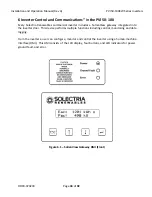
Страница 34: ... includes a SolrenView gateway integrated into the inverter door This device performs multiple functions including control monitoring and data logging From the inverter a user can configure monitor and control the inverter using a human machine interface HMI This HMI consists of the LCD display four buttons and LED indicators for power ground fault and error Figure 6 1 SolrenView Gateway HMI Front...

Страница 35: ...sing Ethernet over twisted pair Third party monitoring systems can be connected to the inverter using Modbus RTU protocol RS 485 WARNING SolrenView gateway connections must be made by qualified personnel only To reduce the risk of electric shock you should never attempt to open the inverter DC or AC enclosure doors or perform any service or troubleshooting without prior training Before attempting ...

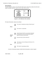
Страница 36: ...D screen allow the installer and user to see the current status of the inverter Power Ground Fault Error CAUTION RISK OF ELECTRICAL SHOCK NORMALLY GROUNDED CONDUCTORS MAY BE UNGROUNDED AND ENERGIZED WHEN A GROUND FAULT IS INDICATED Figure 6 3 LED Indicators at Normal Status The basic LED indicator statuses are as follows For other LED indications please contact Solectria Renewables Customer Suppor...

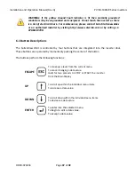
Страница 37: ... Button Descriptions The SolrenView HMI is controlled by four buttons that are integrated into the inverter door These buttons are operated by momentarily pushing the center of the button The buttons perform the following functions ESCAPE To move up a level from the current menu To cancel changing a data value Hold for two seconds to STOP or START the inverter from the Main Display UP To scroll up...

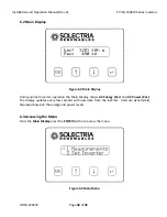
Страница 38: ...ay During normal inverter operation the Main Display shows AC Energy Eac and AC Power Pac The display updates every few seconds with new data from the inverter Units are dynamically displayed based on the energy and power levels 6 3 Accessing the Menu From the Main Display press the ENTER button to access the menu Figure 6 5 Main Menu ...

Страница 39: ...lease note that the display only shows two menu options at a time and will scroll to show the other options Press the DOWN or UP button to change the selected menu option as indicated by the arrow Press the ENTER button to activate the selected function or submenu Hint All menus wrap around Pressing the UP button when the at the top of a menu will select the bottom most menu option Pressing the DO...

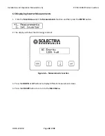
Страница 40: ... Inverter Measurements 1 From the Main Menu select the Measurements function and then press the ENTER button 2 The display will show the AC Energy readout Figure 6 6 Measurements Function 3 Press the DOWN or UP buttons to display different measurement values 4 Press the ESCAPE button to return to the Main Menu ...

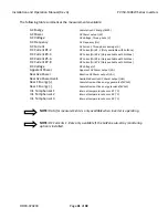
Страница 41: ... available with SolZone DC Current 7 8 DC Current A 7 8 Only available with SolZone DC Voltage DC Voltage V Apparent Power Apparent AC Power output VA Reactive Power Reactive AC Power output VAr Reactive Power Avail Available Reactive AC Power output Var React Energy Cumulative reactive energy generated kVArh React Energy Cumulative reactive energy received kVArh Int Temp Sensor 1 Internal tempera...

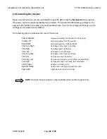
Страница 42: ...Disable Temporarily disables the AC output of the inverter Inverter ID Serial port address ID of the inverter Baud Rate Serial port baud rate 19200 or 9600 Vac Very High AC Voltage Critical High Trip Setting Vac High AC Voltage High Trip Settings Vac Low AC Voltage Low Trip Settings Vac Very Low AC Voltage Critical Low Trip Setting Fac Low AC Frequency Low Trip Setting Fac Very Low AC Frequency Cr...

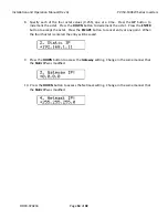
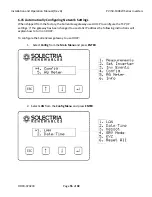
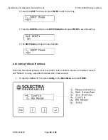
Страница 43: ...Hold down the ESCAPE button for two seconds to temporarily stop the inverter if it is running Likewise hold down the ESCAPE button for two seconds to initiate inverter starting if it is stopped Alternatively the inverter can be started and temporarily stopped through the menu 1 From the Main Menu select the Set Inverter function and then press the ENTER button 2 The Power Stopped status will be di...

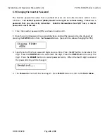
Страница 44: ...e UP button from the top of the Set Inverter submenu as the menu wraps around 3 The Password screen will appear 4 Press the ENTER button to begin entering the default password PIN 5 Specify each of the four PIN digits one at a time Press the UP button to increment the digit Press the DOWN button to decrement the digit Press the ENTER button to accept the digit Press the ESCAPE button to cancel PIN...

Страница 45: ...er the inverter password PIN as shown in section 6 9 2 Once the current password has successfully been entered the password can be changed by pressing the ENTER button from the Password screen Second time allows changing the PIN 3 Specify each of the four password digits one at a time Press the UP button to increment the digit Press the DOWN button to decrement the digit Press the ENTER button to ...

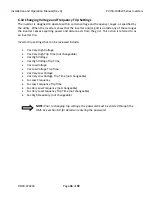
Страница 46: ...s action is referred to as an inverter trip Inverter trip settings that can be reviewed include Vac Very High Voltage Vac Very High Trip Time not changeable Vac High Voltage Vac High Voltage Trip Time Vac Low Voltage Vac Low Voltage Trip Time Vac Very Low Voltage Vac Very Low Voltage Trip Time not changeable Fac Low Frequency Fac Low Frequency Trip Time Fac Very Low Frequency not changeable Fac Ve...

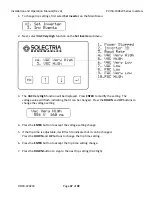
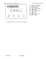
Страница 47: ...NTER to modify the setting The voltage value will flash indicating that it can be changed Press the DOWN and UP buttons to change the voltage setting 4 Press the ENTER button to accept the voltage setting change 5 If the trip time is adjustable it will flash to indicate that it can be changed Press the DOWN and UP buttons to change the trip time setting 6 Press the ENTER button to accept the trip ...

Страница 48: ...Installation and Operation Manual Rev A PVI 50 100KW Series Inverters DOCR 070233 Page 48 of 92 8 Repeat steps 3 6 for each trip setting to be modified ...

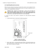
Страница 49: ...ches must be set to the OFF position and the absence of voltage must be verified by qualified personnel Do not rely on HMI functions to stop the inverter as a reset might cause the inverter to start unexpectedly To connect the inverter to the network in preparation for using SolrenView web based monitoring 1 Locate the Ethernet port on the back of the SolrenView gateway Figure 6 7 Ethernet Connect...

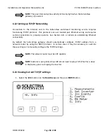
Страница 50: ... connections to properly operate See Section 6 11 or details on establishing Ethernet connectivity By default the SolrenView gateway should automatically configure TCP IP address from a network router by using the DHCP protocol In certain cases it may be necessary to override these settings or to manually configure the TCP IP settings NOTE The network router must be 10T capable NOTE Customers usin...

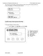
Страница 51: ...ample the IP address gateway and netmask values are being automatically being set through the DHCP service The exact values displayed will depend on the configuration of the network but typically are in one of three ranges 10 0 0 0 10 255 255 255 192 168 0 0 192 168 255 255 172 16 0 0 172 31 255 255 3 If the network is working on the Ethernet protocol level but the SolrenView is unable to obtain s...

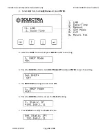
Страница 52: ...of 92 If the network is not working on the Ethernet protocol level such as if the twisted pair Ethernet cable is not plugged in the following will be displayed 6 14 Manually Configuring Network Settings To manually configure network settings 1 Select Config from the Main Menu and press ENTER ...

Страница 53: ...e Config Menu and press ENTER 3 Select the DHCP function and press ENTER to edit this setting 4 Press the DOWN button to turn DHCP Mode Off and press ENTER to save this setting 5 The DHCP Mode setting will now show Off 6 Press the DOWN button to access the Static IP setting 7 Press ENTER to modify the Static IP value ...

Страница 54: ...OWN button to decrement the octet Press the ENTER button to accept the octet Press the ESCAPE button to cancel entry at any point When the fourth octet is entered the entry will be saved 9 Press the DOWN button to access the Gateway setting Change in the same manner that the Static IP was modified 10 Press the DOWN button to access the Netmask setting Change in the same manner that the Static IP w...

Страница 55: ...pped from the factory the SolrenView gateway uses DHCP to configure the TCP IP settings If the gateway has been changed to use static IP address the following instructions will explain how to turn on DHCP To configure the SolrenView gateway to use DHCP 1 Select Config from the Main Menu and press ENTER 2 Select LAN from the Config Menu and press ENTER ...

Страница 56: ...button to turn DHCP Mode On and press ENTER to save this setting 5 The DHCP Mode setting will now show On 6 16 Setting Fallback IP Address When the SolrenView gateway is set to use DHCP but is unable to acquire an IP address lease it will fallback to using a specified IP address after a few seconds 1 To specify a fallback IP first select Config on the Main Menu and press ENTER ...

Страница 57: ...hen DHCP is turned on 4 Press the Down button to show the Fallback IP setting 5 To change the Fallback IP press the ENTER button 6 Specify each of the four octet values 0 255 one at a time Press the UP button to increment the octet Press the DOWN button to decrement the octet Press the ENTER button to accept the octet Press the ESCAPE button to cancel entry at any point When the fourth octet is en...

Страница 58: ...ct the Autodetect option in using the HMI Autodetect is the special gateway value of 0 0 0 0 11 To configure the SolrenView gateway to use a manual gateway specify each of the four octet values 0 255 one at a time Press the UP button to increment the octet Press the DOWN button to decrement the octet Press the ENTER button to accept the octet Press the ESCAPE button to cancel entry at any point Wh...

Страница 59: ...ew web based monitoring service If SRV Mode is turned on and the gateway is unable to transfer data to the monitoring service then data will accumulate in a queue on the SolrenView gateway This queue is stored in non volatile flash memory After a few weeks the data queue will become full and the oldest data will be lost so it is important to establish Internet connectivity soon after the inverters...

Страница 60: ...he setting Press the DOWN button to change the setting to On 4 Press the ENTER button to accept the setting change 6 18 Viewing and setting the Date Time When the SolrenView web based monitoring service is purchased and functioning it is normally not necessary to set or maintain the time on the inverter The time will automatically be set and adjusted based on the inverter s time zone NOTE The date...

Страница 61: ...t select Config on the Main Menu and press ENTER 2 Select the Date Time option on the Config Menu and press ENTER 3 The current date will be displayed If the date can be modified an arrow will appear just before the month Note The date is only editable if SRV Mode is off When SRV Mode is on the date and time is automatically set ...

Страница 62: ...t the year value and save the date to the SolrenView unit s memory 7 After modifying the date the new date will be shown Press the DOWN button to proceed to the time 8 Press the ENTER button to begin changing the time The format is HH MM SS and hours are shown in 24 hour format The hour will flash indicating that this portion of the time can be changed with the buttons Press the UP button to incre...

Страница 63: ...View Gateway cannot communicate over the Internet or is not updating inverter data it may need to be rebooted To reboot SolrenView gateway 1 First select Config on the Main Menu and press ENTER 2 Select the Reboot option from the menu and press ENTER 3 The Reboot monitor prompt will be shown Press the ENTER button to reboot the SolrenView gateway ...

Страница 64: ...efaults This does not reset the inverter core nor shutdown the inverter for any period of time NOTE Resetting the SolrenView gateway will also clear events revenue grade KYZ counters and SolrenView com data queue Caution should be used with this function to avoid data loss To reset the SolrenView gateway 1 First select Config on the Main Menu and press ENTER 2 Select the Reset All option from the ...

Страница 65: ...ults The Reset Storage screen will appear for a moment 6 21 Inverter Counts and Logs The inverter keeps track of various events and errors through error logging and cumulative counters Error logs are a record of events changes of state with the earliest event shown first There are a total of 30 log entries available and newer entries overwrite older entries Each entry in the log is time stamped in...

Страница 66: ...eration Manual Rev A PVI 50 100KW Series Inverters DOCR 070233 Page 66 of 92 6 22 Displaying Error Counts 1 Select Inv Events from the Main Menu and press ENTER 2 Select Err Counts from the Inv Events Menu and press ENTER ...

Страница 67: ...ged with the last one logged on Jan 02 2013 at 7 12 am The data format is index number date time and occurrences on the first line The second line is the type of the event 4 Press the DOWN button to see the next Error Count entry Continuing our example the second most frequent error is Lost Frequency lock which occurred once on Jan 01 2013 at 7 10 am 5 If no Count data is recorded the date and tim...

Страница 68: ...Operation Manual Rev A PVI 50 100KW Series Inverters DOCR 070233 Page 68 of 92 6 23 Displaying Error Logs 1 Select Inv Events from the Main Menu and press ENTER 2 Select Err Logs from the Inv Events Menu and press ENTER ...

Страница 69: ...e event state is shown as Off The second line is the type of the event 4 Press the DOWN buttons to see the next event stored in the log In this example the inverter asserted a Lost Freq Lock error on Jan 01 2013 at 7 10 am and ceased to assert the Lost Freq Lock error on Jan 01 2013 at 7 11 am 5 If no Events are recorded the date and time that the Events were last cleared is displayed 6 Press the ...

Страница 70: ...ear from the Inv Events Menu and press ENTER The Clear History prompt will be shown Select the type of history to be cleared by pressing the UP and DOWN buttons Press ENTER to clear the history based on one of these settings Press the ESCAPE button to cancel None History is not cleared Err Log Clears the Error Log only Err Counts Clears the Error Counts only All Clears the Error Counts and Error L...

Страница 71: ... CT Failure DC GND FAULT DC Voltage High Desat Error DMGI Overtemp Fan Life Reached IGBT Overtemp Lost Freq Lock MAG Fail Min Vmpp Reached MOV Fault NTC Failure Open Phase Power Derated Power stage failure PS Wake Fail VDC Ctrl Fail Vsense Err List of Displayed Events The following events are frequently encountered or events that only occur during installation AC Disconnect switch DC Disconnect sw...

Страница 72: ...Installation and Operation Manual Rev A PVI 50 100KW Series Inverters DOCR 070233 Page 72 of 92 6 25 HMI Menu Structure ...

Страница 73: ... ambient temp fans operating vents are clear AC wire sizing The AC grid voltage is exceeding the high limit Measure the actual VAC compared to the LCD display VAC If VAC is greater than acceptable limits the inverter will restart when VAC returns to normal range The AC grid voltage is less than the low limit Measure the actual VAC compared to the LCD display VAC If VAC is less than acceptable limi...

Страница 74: ... voltage condition and is in the 5 minute reconnect wait Wait for the inverter to restart Grid voltage may not be present Check for grid voltage on all phases The VAC grid connection phasing does not match the inverter s phasing Swap two of the phase wire positions at the inverter AC wiring terminals in the AC disconnect switch then restart The power point tracking has been reached The inverter wi...

Страница 75: ...wables if malfunction persists If contacting Solectria Renewables for assistance please provide 1 Inverter Model Number Part Number 2 Inverter Serial Numbers 3 Short Description of Problem LCD messages when problem started how often problem occurs under what conditions the problem occurs 4 Design Information PV modules string sizing output power short circuit current and open circuit voltage strin...

Страница 76: ... should be shipped to Solectria Renewables for repair or replacement be sure to get an RMA from Solectria Renewables and use the same packing method as when it was shipped to you or request instruction on packing and or packing materials from Solectria Renewables to help insure a safe shipment 7 3 Preventative Maintenance WARNING These maintenance instructions are for use by qualified personnel on...

Страница 77: ...hout removing the vent use a powerful vacuum and clean entire louver vent screen Method 2 Remove the shroud by removing all Philips Pan Head 2 machine screws around the shroud sides and top and remove the shroud Next remove the remaining bottom screws holding the louver vent onto the inverter Use compressed air from the back insect screen side of the louver vent screen unit to remove all debris Re...

Страница 78: ...en with inverter off and DC Disconnect Switch open 1 Disconnect inverter from DC power from array to ensure that live DC is not entering DC disconnect switch enclosure 2 Use the SolrenView HMI keypad to temporarily disable the power output by pressing and holding the ESCAPE button for two seconds 3 Switch off DC disconnect switch 4 Switch off AC disconnect switch 5 Watch until all LED indicators h...

Страница 79: ...08V 175A 225A 300A 300A 350A 240V 150A 200A 225A 300A 300A 480V 110A 110A 125A 150A 150A 600V 110A 110A 110A 110A 125A Table 7 1 AC Disconnect Switch Fuse Specifications DC Input Fuses if equipped WARNING If inverter is equipped with the fused PV sub combiner fuses in DC disconnect switch must only be replaced with 600VDC rated fuses of the same type Always refer to PV module and combiner fuse rat...

Страница 80: ...has been purchased the term is defined as an extension beyond 60 months For example if a 5 year extension to 10 years total is purchased the term becomes 120 months from date of purchase For the PVI 3000 to PVI 7500 inverters the warranty period is 120 months from the date of purchase by the end user or 124 months after the delivery date from Solectria Renewables to the distributor or the dealer i...

Страница 81: ...uous United States Canada and Mexico For Alaska Hawaii and all other installation locations Solectria Renewables will supply necessary parts as needed for warranty repairs however travel is not included Contact Solectria Renewables customer service for details on the freight policy for return shipments outside of the contiguous United States Canada and Mexico Obtaining Service If your product requ...

Страница 82: ...o a The product if it has been misused neglected improperly installed physically damaged or altered either internally or externally or damaged from improper use or use in an unsuitable environment b The product if it has been subjected to fire water generalized corrosion biological infestations acts of God or input voltage that creates operating conditions beyond the maximum or minimum limits list...

Страница 83: ...WABLES INCLUDING ITS SUPPLIERS MANUFACTURERS VENDORS SUBCONTRACTORS DISTRIBUTORS DEALERS AND ANY OTHER AFFILIATES BE LIABLE FOR ANY SPECIAL DIRECT INDIRECT INCIDENTAL OR CONSEQUENTIAL DAMAGES LOSSES COSTS OR EXPENSES HOWEVER ARISING WHETHER IN CONTRACT OR TORT INCLUDING WITHOUT RESTRICTION ANY ECONOMIC LOSSES OF ANY KIND ANY LOSS OR DAMAGE TO PROPERTY INCLUDING LOSS OF USE AND INTANGIBLE HARM OF A...

Страница 84: ... b ASSUMES NO RESPONSIBILITY OR LIABILITY FOR LOSSES DAMAGES COSTS OR EXPENSES WHETHER SPECIAL DIRECT INDIRECT CONSEQUENTIAL OR INCIDENTAL WHICH MIGHT ARISE OUT OF THE USE OF SUCH INFORMATION THE USE OF ANY SUCH INFORMATION WILL BE ENTIRELY AT THE USERS RISK WARNING LIMITATIONS ON USE Please refer to your product user manual for limitations on uses of the product Specifically please note that Sole...

Страница 85: ...the unit safely preferably using the original box and packing materials Please ensure that your product is shipped fully insured in the original packaging or equivalent This warranty will not apply where the product is damaged due to improper packaging 2 Include the following a The RMA number supplied by Solectria Renewables clearly marked on the outside of the box b A return address to which the ...

Страница 86: ...temperature conditions Both the maximum open circuit voltage OCV when at maximum cold temperatures and minimum MPPT voltage when at maximum hot temperatures can be calculated for a PV module using its specification sheet PV module string sizing can then be used to determine how many modules can be used in a string Visit http www solectria com page_id 30 to use Solectria Renewables interactive stri...

Страница 87: ...s designed to work with the range of AC voltages for a three phase service defined by IEEE 1547 2003 and ANSI C84 1 PVI 50KW PVI 60KW PVI 75KW 75KW PE PVI 85KW 85KW PE PVI100KW 100KW PE Unit Operating AC voltage range 88 110 Turn on AC voltage range 92 105 Operating frequency Default 59 3 60 5 Hz Continuous Output Power 50 60 75 85 100 kW Continuous Output Current 208VAC 139 167 208 236 278 Arms 2...

Страница 88: ...Adjustment Range Frequency Limit Hz Clearing Time s Frequency Limit Hz Clearing Time s Underfrequency fast 81U f 57 0 0 16 f 57 0 fixed 0 16 Underfrequency slow 81U f 59 3 0 16 f 57 0 to 59 8 0 16 to 300 Overfrequency fast 81O f 60 5 0 16 f 60 5 fixed 0 16 Table 8 4 Frequency Trip Settings 8 3 Other Specifications Operational Ambient Temperature full power 40ᵒ to 55ᵒC 40ᵒF to 131ᵒF Storage Tempera...

Страница 89: ...ual Rev A PVI 50 100KW Series Inverters DOCR 070233 Page 89 of 92 Figure 8 1 AC Output Power vs DC Input Voltage of PVI 50 100KW Series Inverters Strike Voltage Standard Strike Voltage LV Option MPPT Min Standard MPPT Min LV Option ...

Страница 90: ... Page 90 of 92 8 4 Internal Circuit Diagram The basic power flow within the PVI 50KW 100KW series inverters is shown in the simplified one line diagram below Note that grounding and GFDI circuit is not depicted Figure 8 2 Simplified One Line Diagram of PVI 50 100KW Series Inverters ...

Страница 91: ...dix B String Sizing Tool http www solectria com page_id 30 9 3 Appendix C Contact Information Solectria Renewables LLC 360 Merrimack Street Building 9 2nd floor Lawrence Massachusetts 01843 USA Tel 978 683 9700 Fax 978 683 9702 Sales General Info inverters solectria com Customer Support service solectria com Website www solectria com 9 4 Appendix D Authorized Distributors See website for complete ...

Страница 92: ...Installation and Operation Manual Rev A PVI 50 100KW Series Inverters DOCR 070233 Page 92 of 92 9 5 Appendix E UL1741 IEEE 1547 Authorization Letter to Mark Product ...

Отзывы: