


Dyaco Canada Inc. 2013
9
#112.
3/8” x 3-3/4” Hex
Head Bolt (4 pcs)
#113
. 3/8” x 3/4” Socket
Head Cap Bolt
(4 pcs)
#119.
M5 x 10mm
Phillips
Head Screw
(4 pcs)
#139
. 3/8” x 19mm x
1.5T
Flat Washer (4 pcs)
#142.
3/8” x2T Split
Washer (8 pcs)
#144
. 3/8” x 23 x 2T
Curved Washer (4 pcs)
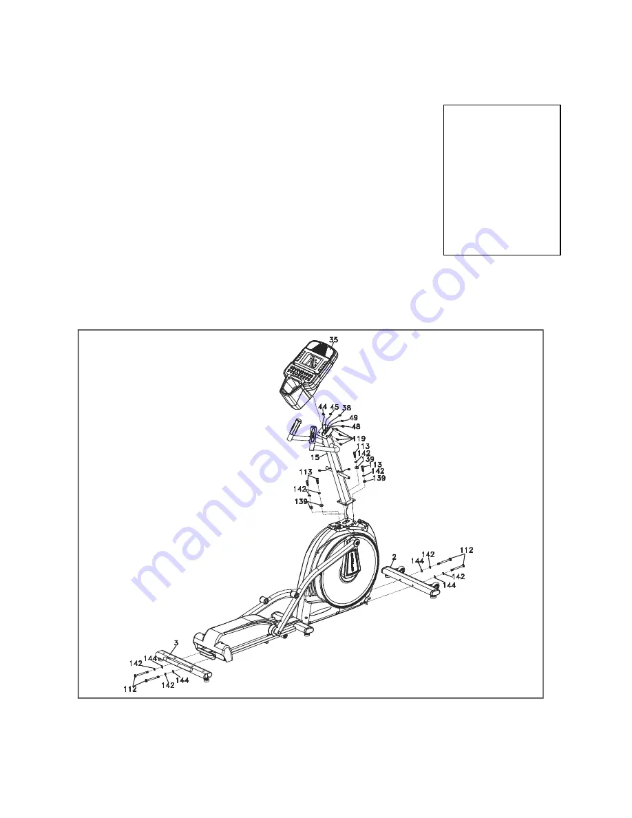
ASSEMBLY INSTRUCTIONS
1
STABILIZERS
& CONSOLE
MAST
HARDWARE
STEP 1
1.
Connect the Front Stabilizer Bar (
2
) with the Main Frame at the front
joining
plate by using the Wrench (
151
) to tighten two Hex Head Bolts
(
112
) , two
Split Washers (
142
) and two Curved Washers (
144
).
2.
Connect the Rear Stabilizer (
3
) with the Main Frame at the rear joining
plate
by using the Wrench (
151
) to tighten two Hex Head Bolts (
112
) ,
two Split
Washers (
142
) and two Curved Washers (
144
).
3.
Pull the wire, which is attached to the Computer Cable (
38
), out of
Console
Mast (
15
) and secure the mast on the Main Frame by using the
M8 L Allen
Wrench (
153
) to tighten four Socket Head Cap Bolts (
113
)
together with four
Split Washers (
142
) and four Flat Washers (
139
).
4.
Plug in the connectors of the Computer Cable (
38
) and two Handpulse
with
Cable Assemblies (White & Red) (
44
,
45
) on the back of the
Console Assembly
(
35
) and secure the Console Assembly (
35
) on the
console holding plate
with four Phillips Head Screws (
119
) by tightening
them with Phillips Head Screw Driver (
150
).
ASSEMBLY
STEP 1


