SR971,SR972 Solar station operation manual
-------------------------------------------------------------------------------------------------------------------------------------
0
Страница 1: ...SR971 SR972 Solar station operation manual 0...
Страница 2: ...rol operation description 15 6 1 Operation button 15 6 2 Signal description 16 6 3 Time week setup 17 6 4 Menu structure 18 6 5 Menu description 19 6 6 System description 21 6 6 1 System 1 collector a...
Страница 3: ...perature difference for circuit pump s speed adjusting 40 7 7 4 Submenu OHQM Thermal energy measuring 40 7 7 5 Submenu FMAX Flow rate 42 7 7 6 Submenu MEDT Type of heat transfer liquid 42 7 7 7 Submen...
Страница 4: ...971 SR972 Solar station operation manual 3 9 1 Trouble protection 52 9 2 Trouble checking 53 10 Quality Guarantee 55 11 Technical data 56 12 Delivery scope 57 13 Devices matchable to this controller 5...
Страница 5: ...nsibility and liability for losses damages or cost that might arise due to improper installation operation or wrong utilization and maintenance or that occur in some connection with the aforementioned...
Страница 6: ...in the text are marked with a warning triangle They indicate measures which can lead to injury of persons or safety risks Operation steps small triangle is used to indicate operation step Notes Contai...
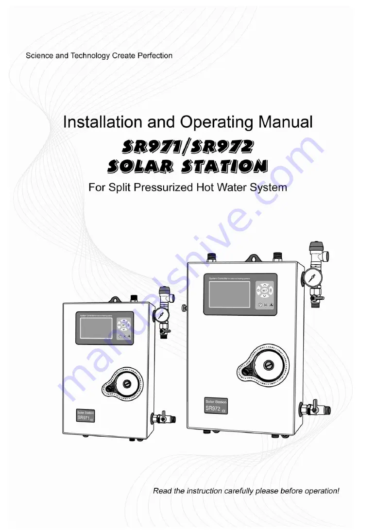
Страница 7: ...3 Connection to collector male thread G1 2 2 4 Safety valve 6bar 2 5 Solar circulation pressure gauge measure range 0 10bar 2 6 Discharge filling valve connection male thread G1 2 integrated together...
Страница 8: ...ank male thread G1 2 2 15 Connection to tank male thread G1 2 not exist on SR971 2 16 Air saperator including manual release valve not exist on SR971 2 17 Return pipe temperature sensor NTC10K B 3950...
Страница 9: ...ax permitted pressure 10 bar Max permitted temperature 130 Pipe connections 4 G1 2 for SR972 Or 2 G1 2 for SR971 male thread Safety devices Safety valve pressure 6bar Manometer 0 10bar Connector for e...
Страница 10: ...min Air seperator no in SR971 Connections for flushing filling unit For hose fitting G1 2 Thermal insulation Material for back and front casing EPS EPP 2 kinds of material can be chose Material for fr...
Страница 11: ...ion operation manual 10 3 Mounting of solar station Drill the upper fixing hole Fasten the screw Mark the bottom fixing hole Drill the bottom hole Fasten the bottom screw 4 Attention Items for solar s...
Страница 12: ...ain off discharge from the safety valve using a copper pipe correctly and in an eco friendly way according to valid technical regulations and load codes do not allow solar fluid to leak into the envir...
Страница 13: ...oosen the fixing screw B which is on the back of connection box Pull out the connection box downwards parallelly C Loosen the protection screw D open the cover of terminal upwards Using proper tools l...
Страница 14: ...peration manual 13 Note Please use delivered clamps to fix wires correctly F 5 2 Change fuses Use screw driver see as picture turn to left to spring fuse fuse parameter AC250V 6 3A 5 3 Terminal connec...
Страница 15: ...y equipped NTC10K B 3950 temperature sensors are approved for use with tank and pipe it is equipped with 1 5meter PVC cable and the cable are temperature resistant up to 105 o C not necessary to disti...
Страница 16: ...al heater Note Solar pump installed on solar station is already connected with controller eletronmagnetic valve and sensor connections relay on the system you selected Shielded cable should be used eB...
Страница 17: ...e Signal Display Flash display Electrical heater is in active Collector safety temperature function is in active Tank urgency stop funtion is in active Collector cooling function is in active Collecto...
Страница 18: ...to adjust hour of clock Repress 00 of minute area blinks Press to adjust minute of clock Repress MO of week blinks Press to adjust weekday Press ESC to exit setup menu or wait for 20 seconds to exit s...
Страница 19: ...SR971 SR972 Solar station operation manual 18 6 4 Menu structure Submenu Through submenu you can setup more detailed please make sure to understand the content in submenu...
Страница 20: ...tor 9 CFR Frost protection temperature of collector 10 REC Tank recooling function 11 SMX1 Maximum temperature of tank 1 12 C F C F temperature display transferring 13 FUN Auxiliary functions 14 DVWG...
Страница 21: ...SR972 Solar station operation manual 20 25 AHO AHF Tank thermostat function 26 COOL Tank cooling at high temperature function 27 HDN Manual operation 28 PASS Passowrd setup 29 REST Recovery to factory...
Страница 22: ...on of back up heating if the temperature T3 of tank drops below the switch on temperature then the circulation pump H1 of back up heating is triggered when T3 is heated to the switch off temperature c...
Страница 23: ...SET button again the third digital blinks Press button to enter the third digital of password Press SET button again the fourth digital blinks Press button to enter the fourth digital of password Pres...
Страница 24: ...e section back up heating function starts at 17 00 and ends at 22 00 pm Within this time section the switch on temperature is 50 o C switch off temperature is 55 o C The switch on temperature adjustab...
Страница 25: ...k Press SET button again 00 of minute area blinks Press button to adjust minute Repress SET button to shift to temperature area 40 blinks Press button to adjust switch on temperature Press ESC button...
Страница 26: ...shift to temperature area 55 blinks Press button to adjust switch off temperature Press ESC button to exit submenu or wait for 20 seconds to exit setup parameter is saved automatically Press button t...
Страница 27: ...ng with SR802 device with this controller SR802 detailed technical data see in 13 part For example 7 4 Main menu tCYC In three time sections temperature and time control DHW hot water Function descrip...
Страница 28: ...for DHW pump when controller detects return pipe T5 temperature controller will trigger temperature controlled DHW pump and at same time close time controlled DHW pump tCYC menu is used for setting ti...
Страница 29: ...on to adjust DHW pump interval time when installed T5 sensor here will ask for adjust switch off temperature Press ESC button to exit submenu or wait for 20 seconds to exit setup parameter are saved a...
Страница 30: ...blinks Press button to adjust minute Repress SET button to shift to operation time set 03 Min blinks Press button to adjust DHW pump operation time when installed T5 sensor here will ask for adjust sw...
Страница 31: ...g far distance heat transferring normally it is recommend to use default set Switch on and switch off DT are alternating set To avoid mistake the minimum difference between two temperature differences...
Страница 32: ...ccess though TEMP main menu EMOF Collector safety switch off temperature 7 6 1 EMON Collector safety recovery temperature 7 6 1 CMX Maximum limited collector temperature collector cooling function 7 6...
Страница 33: ...collector temperature drops to the safety recovery temperature EMON factory set 120 o C solar circuit pump restarts and at the same time this function is deactivated Setup steps EMOF Collector safety...
Страница 34: ...rtly before reaching the maximum temperature of the collector the solar pump starts working in order to cool down the heat transfer fluid using the heat losses occurring in pipelines and storage cylin...
Страница 35: ...ven when the temperature difference between collector and tank exceeds the switch on temperature difference solar pump doesn t work yet When temperature of collector is 3 o C over the preset CMN tempe...
Страница 36: ...fer fluid Setup steps To access main menu TEMP then select submenu CFR CFR displays on screen default set is off Press SET button default off blinks Repress SET button to activate or deactivate this f...
Страница 37: ...on to exit the menu or wait for 20 seconds to exit parameters are saved automatically REC signal displays on screen it indicates this function is activated 7 6 6 Submenu SMX1 Maximum temperature of ta...
Страница 38: ...matically 7 7 Main menu FUN Auxiliary function The auxiliary function of this controller can be set under FUN submenu it is possible to activate several auxiliary functions at the same time Activated...
Страница 39: ...e factory set default time 01 00 on the seventh day of the period auxiliary heating system is triggered automatically to heat water until it rises up to 70 o C bacteria is killed by high temperature w...
Страница 40: ...is deactivated pump is operated with a fixed speed 100 and flow rate is not changed RPM control output speed controlling is activated the control attempts to maintain a constant temperature difference...
Страница 41: ...ard temperature difference DTS If temperature difference drops to the switch off TD T OFF circuit pump is ceased Setup steps To access main menu FUN then select submenu DTS DTS 08 o C displays on the...
Страница 42: ...n steps under standby status doing like following Press button select to check the thermal energy of current day DKWH XX SET displays on the screen Press SET button for 3 seconds buzzer makes 3 times...
Страница 43: ...DT Type of heat transfer liquid MEDT type of heat transfer liquid adjustable range 00 03 factory set 01 Type of heat transfer liquid 00 Water 01 Propylene glycol 02 Glycol 03 Tyfocor LS G LS Setup ste...
Страница 44: ...mp is in no operation status because of invalid temperature difference Every 30 minutes it is set in parameter ISTP controller triggers circulation pump for 10 seconds it is set in parameter IRUN it w...
Страница 45: ...set is 10 Repress button to adjust value adjustable range 5 120 second Press ESC button to exit the menu or wait for 20 seconds to exit parameters are saved automatically 7 7 9 Submenu AHO AHF Tank th...
Страница 46: ...C factory set 7 o C AHO signal displays on the screen indicates this function is in operation Note Temperature sensor T4 is not included within standard delivery it should purchase seperately Heat lo...
Страница 47: ...neously too Setup steps To access main menu FUN then select submenu COOL COOL displays on screen Press SET button blinks on the screen Factory set is off Repress SET button to activate this function C...
Страница 48: ...put of R1 is close Press ESC button to exit R1 set Press button HND2 off blinks on the screen it is ready to start R2 manual set Repress SET button HND2 on blinks output of R2 is activate Repress SET...
Страница 49: ...utput is closed automatically And controller exits manual function 7 9 Mainmenu PASS Password setup Setup steps To access main menu PASS Press SET button PWDC 0000 shows on the screen left digital bli...
Страница 50: ...itch off power of controller press SET button and hold on then switch on power buzzer makes du 3 times release SET button password recoverys to factory set 0000 then you can set a new password again 7...
Страница 51: ...be absent for an extended period holiday No hot water is required for an extended period When the temperature in bottom of storage tank drops below 35 o C Activate deactivate this function Press butto...
Страница 52: ...preset temperature manual heating ceases and manual heating function will be deactivated automatically if customer wants to heat again you need redo according to above steps 7 14 Temperature query fun...
Страница 53: ...er switches off the corresponding functions and corresponding output signals at the same time error signals are showed on the display If control unit does not work correctly please check following poi...
Страница 54: ...the list below only return the controller to seller when you are absolutely sure that none of the problems listed below is responsible for the fault Symptoms Secondary symptoms Possible cause Procedur...
Страница 55: ...n t be activated There is no function selection in submenu All inputs and outputs are used inputs and outputs can t be used doubly No fault on controller Pump works but flow rate shows 0 0L min No fil...
Страница 56: ...oduction and material selection A correct installation will not lead to failure When a user takes incorrect handling way incorrect installation improper or crud handling wrong connection of sensor in...
Страница 57: ...valve 4 600W Suitable power of electrical heater 1 600W Inputs Total 5 sensor thereof 4 sensors are standard 1 sensors are optinal 1 x Pt1000 sensor 500 o C for collector T1 silicon cable 280 o C 3 x...
Страница 58: ...A 1 piece 13 Device matchable to this controller PT1000 sensor A01 for high temperature use for collector Size PT1000 6 50mm 1 5m silicon cable NTC10K B 3950 snesor A02 for tank Size NTC10K B 3950 6 5...
Страница 59: ...SR971 SR972 Solar station operation manual 58 SR802 connection example Note only qualified person can connect SR802...