13
Safety, Installation, and Operations Manual
©2021 The Solaria Corporation All rights reserved. Contents subject to change without notice. AUS-MAN-0002 Rev 01, 03-2021
Power Unlocked by Design
6.4 Bypass Diodes
Do not contact organic solvents and other corrosive materials in connector connection and the use environment,
such as alcohol, gasoline, pesticides, herbicides, etc.
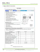
The junction boxes used with Solaria Solar Modules contain bypass diodes wired in parallel with the PV cell strings.
In the case of partial shading, the diodes bypass the current generated by the non-shaded cells, thereby limiting
Modules heating and performance losses. Bypass diodes are not over-current protection devices.
In the event of a known or suspected diode failure, installers or maintenance providers should contact Solaria. Never
attempt to open the junction box by yourself.
Please pay attention to guard against inductive lightning, backflow and wrong connection.
7.0 Grounding
Solaria Solar Modules use an anodized aluminum frame to resist corrosion. The Module frames should be
connected to the equipment grounding conductor to prevent electrical shock due to lightening.
The grounding device should fully contact with the inside of the aluminum alloy, and penetrate the surface of the
frame oxidation film.
Please don’t drill any additional grounding hole on the frame of the Modules, otherwise it will expressly void the
Solaria warranty.
For optimal performance, Solaria Solar Modules should only be used in configurations where the DC cathode (-) of
the Modules array is connected to ground. Failure to comply with this requirement will reduce the performance of
the system.
The grounding method should not result in the direct contact of dissimilar metals with the aluminum frame of the
Modules that will result in galvanic corrosion. IEC 60950-1 standard recommends metal combinations not exceed
an electrochemical potential difference of 0.6 Volts.
The frame rails have pre-drilled holes marked with a grounding sign. These holes should be used for grounding
purposes and should not be used for mounting the Modules.
The following grounding methods are available.
7.1 Grounding By Using Grounding Bolt
There are two grounding holes with 4.5 mm diameter on each of the long edges of the back frame of the Modules.
The grounding between Modules must be approved by a qualified electrician. The grounding device should be
produced by a qualified electrical manufacturer. The recommended torque value is 2.3 N.m. A 12 AWG copper wire
can be used as the equipment grounding conductor in conjunction with the grounding bolt. The copper wire should
not be compressed during the installation.

