UPS for 400 Vac Grid, Installation Guide, doc. rel. 3.0
89
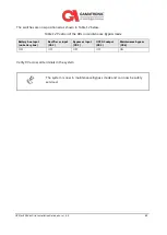
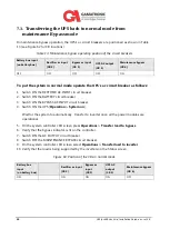
The switches are now positioned as shown in Table 12 below.
Table 12: Position of the CBs in maintenance Bypass mode
Battery box input
(on battery box)
Rectifier ac input
(CB 2)
Bypass ac input
(CB 3)
UPS AC output
(CB 5)
Maintenance bypass
(CB 6)
OFF
OFF
OFF
OFF
ON
Verify 0V across all terminals in the system.
The system is now in maintenance Bypass mode and can now be safely
serviced.
Содержание Gamatronic B300
Страница 91: ...UPS for 400 Vac Grid Installation Guide doc rel 3 0 83 Figure 60 Connection diagram for 2 parallel units ...
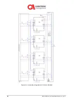
Страница 92: ...84 UPS for 400 Vac Grid Installation Guide doc rel 3 0 Figure 61 Connection diagram for 4 Units in Parallel ...
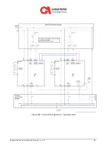
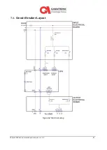
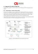
Страница 95: ...UPS for 400 Vac Grid Installation Guide doc rel 3 0 87 7 1 Circuit Breaker Layout Figure 62 Electrical setup ...

