December 2020
|
Solar Stik
®
, Inc.
22
|
System Setup and Operation Manual for the Solar Stik G-BOSS E Light HPS
PRELIMINARY
The bottom of the PDM 3000 case is cut away to facilitate heat dissipation. The internal components
are sealed from exposure to the environment by a gasket.
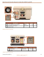
Output Breakers
Regulated 28 VDC
to PDU
Figure 8. PDM right side
The 2-pin connector on the right side of the PDM 3000 provides regulated 28.0 VDC power to the
G-BOSS Power Distribution Unit (PDU). The 100 A breakers on the right side also serve as power
switches for engaging and disengaging power circuits to the tower and the PDU.
CAUTION
Do NOT connect a battery directly to the regulated 28 VDC output port because this
will damage the PDM 3000.
Description
Connector
Voltage
Amps
A
28.0 VDC regulated output
Amphenol?
28.0 VDC
75
B
Regulated 28 VDC Output to PDU
N/A
N/A
100
C
24 VDC Output to Tower
N/A
N/A
100
A
B
C
Figure 9. PDM bottom


