


Manual 2100-707D
Page
21 of 39
However, three phase compressors will rotate in either
direction depending upon phasing of the power.
Since there is a 50-50 chance of connecting power
in such a way as to cause rotation in the reverse
direction, verification of proper rotation must be made.
Verification of proper rotation direction is made by
observing that suction pressure drops and discharge
pressure rises when the compressor is energized.
Reverse rotation also results in an elevated sound level
over that with correct rotation, as well as substantially
reduced current draw compared to tabulated values.
Verification of
proper rotation
must be made at the time
the equipment is put into service. If improper rotation
is corrected at this time, there will be no negative
impact on the durability of the compressor. However,
reverse operation for over 1 hour may have a negative
impact on the bearing due to oil pump out.
NOTE:
If compressor is allowed to run in reverse
rotation for an extended period of time, the
compressor’s internal protector will trip.
All three phase compressors are wired identically
internally. As a result, once the correct phasing is
determined for a specific system or installation,
connecting properly phased power leads to the same
Fusite terminal should maintain proper rotation
direction.
The direction of rotation of the compressor may be
changed by reversing any two line connections to the
unit.
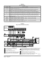
Phase Monitor
All units with three phase scroll compressors are
equipped with a three phase line monitor to prevent
compressor damage due to phase reversal.
The phase monitor in this unit is equipped with two
LEDs. If the Y signal (call for cooling) is present at the
phase monitor and phases are correct, the green LED
will light.
If phases are reversed, the red fault LED will be lit and
compressor operation is inhibited.
If a fault condition occurs, reverse two of the supply
leads to the unit.
Do not reverse any of the unit factory
wires as damage may occur.
Condenser Fan Operation
NOTE:
Certain models may be equipped with a low
ambient control (LAC), and if so, the condenser fan
motor will have a delayed start until system refrigerant
operating pressure builds up. After starting, the fan
motor may or may not cycle depending upon ambient
conditions. This is normal operation.
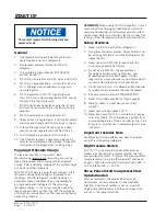
Service Hints
1. Caution owner/operator to maintain clean air filters
at all times and also not to needlessly close off
supply and return air registers. This reduces airflow
through the system, which shortens equipment
service life as well as increasing operating costs.
2. Check all power fuses or circuit breakers to be sure
they are the correct rating.
3. Periodic cleaning of the outdoor coil to permit full
and unrestricted airflow circulation is essential
.
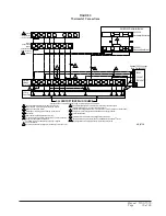
Sequence of Operation
Circuit R-Y1 makes at thermostat pulling in compressor
contactor, starting the compressor and outdoor motor.
(See
NOTE
under
CONDENSER FAN OPERATION
concerning models equipped with low ambient control.)
The G (indoor motor) circuit is automatically completed
by the thermostat on any call for cooling operation or
can be energized by manual fan switch on subbase for
constant air circulation. On a call for heating, circuit
R-W1 makes at the thermostat pulling in heat contactor
for the strip heat and blower operation. On a call for
second stage heat, R-W2 makes bringing on second
heat contactor, if so equipped.
Balanced Climate
TM
Mode
Balanced Climate™ is a great comfort feature that can
easily be applied under any normal circumstances. If
the air conditioning system is being set up in a typical
environment where 72°F is the lowest cooling setpoint,
remove the Y1/Y2 jumper and install a 2-stage cooling
thermostat. This will increase the humidity removal
up to 35% and provide a much more comfortable
environment.
If the application is likely to require air conditioning
operation below 60°F outdoor conditions, a low
ambient control (LAC) kit must be installed.
The LAC
kit is equipped with an outdoor temperature switch
that disables Balanced Climate mode when the outdoor
temperature drops below 50°F. This prevents potential
evaporator coil freeze up issues. The LAC kit also
comes with an evaporator freeze protection thermostat
that cuts out the compressor if the evaporator begins to
freeze up.
If the unit is being installed with any ventilation
package, an LAC kit must be installed.
Failure to utilize
an LAC with any air conditioner can cause coil freeze
up.
Balanced Climate can readily be applied to duct-free
(supply and return air grille) applications. It may also
be applied to ducted applications with
limited static
of 0.20" ESP (total including both supply and return
statics)
. Consult Bard Application Engineering for
details prior to implementation.
CAUTION:
Balanced Climate is not a replacement for
a dehumidification (hot gas reheat) unit for extreme
applications, but rather an enhancement feature for
limited climates and applications.


