Page: 3
P
C
I-
S
lot
-S
el
ec
t
(A
)
(B
)
PCI slot selection
Termination
ON
CAN1
Drain (CAN1)
St
a
tu
s
-L
ED
Jumper (A)
Jumper (B)
PCI slot number
open open 0
(default)
closed open
1
open closed
2
closed closed
3
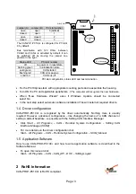
The CAN-PO1-PC104+ is configured for PCI slot
0 by default.
Bus termination with 120 Ohms between
CAN-H and CAN-L is activated by default. It can
be switched off by moving the jumper one
position to the right.
Status-LED
PCI slot number
off
no power or in reset state
flashing green
in initialization state
solid green
CAN started
flashing red
CAN error passive
solid red
CAN bus off
•
Fix the PC/104plus stack with appropriate mounting parts and reassemble the housing.
•
Turn ON the PC and applicable peripherals.
->
The computer will recognize the new hardware.
•
When “New Hardware Wizard” asks if Windows Update should be connected
select
No
.
•
In the next step select
automatic software installation.
This will install all required drivers.
1.4 Driver configuration
CAN-PRO1-PC104+ is recognized by the driver automatically. Nothing more is usually
required. However, advanced configuration – like changing the name of a CAN channel or
setting a default baudrate - is possible with the Softing CAN Interface Manager.
•
Click
Start – All Programs – CAN – Runtime System Configuration – Softing CAN
Interface Manager (SCIM)
•
For more details on the driver configuration click
Start – All Programs – CAN – Runtime System Configuration – SCIM_Manual
1.5 Application Software
How to use CAN-PRO1-PC104+ and how to write application software, is described in the
Software Manual.
•
To open this manual click
Start – All Programs – CAN – CAN_API - DOC – Softing Layer2
2
RoHS Information
CAN-PRO1-PC104+ is RoHS compliant.
PCI slot configuration, status LED and bus termination


