


Page: 3
Table 1: I/O address selection (1=ON, 0=OFF)
DIP switch (S2)
I/O Range
(hex)
1 2 3 4 5 6 7 8
0 1 1 0 1 1 1 1 240-243
0 1 1 0 1 1 1 0 244-247
0 1 1 0 1 1 0 1 248-24B
0 1 1 0 1 1 0 0 24C-24F
0 1 0 1 1 1 1 1 280-283
0 1 0 1 1 1 1 0 284-287
0 1 0 1 1 1 0 1 288-28C
0 1 0 1 1 1 0 0 28C-28F
Table 2: I/O base address values (OFF)
DIP
switch
Value (hex)
1
200
2
100
3
80
4
40
5
20
6
10
7
8
8
4
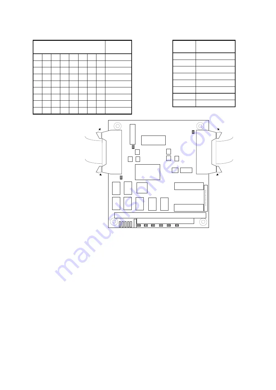
PC/104-
connector
open
open
CAN-104 V1.00
S# xxxxxxx
S2
8
1
open
open
J1
16 pin
X10
16 pin
X13
D-SUB 9 or
interface adapter
CAN 2
D-SUB 9 or
interface adapter
CAN 1
DIP switch for
I/O address
setting
J9
1.4 Driver configuration
CAN-ACx-104 needs to be added to the runtime configuration, by the following steps.
•
Click
Start – All Programs – Softing CAN – Runtime System Configuration – Softing CAN
Interface Manager
•
Select the CAN-ACx-104 branch of the tree view at the left side and click
Add.
•
Enter the information you are asked for and proceed with the
Next
button.
•
The board will then be added to the system configuration.
•
For more details on the driver configuration click
Start – All Programs – Softing CAN – Runtime System Configuration – SCIM Manual
2 Pin Assignment
The D-Sub 9 connectors are replaceably plugged into the PC/104 interface by a 16 pin
ribbon cable connector (see Figure 1). They can be individually fixed at the housing of the
PC as required by the customers system. The pinning of the D-Sub 9 connectors is defined
according to the CiA recommendation for the CAN High Speed Bus The shield is connected
to earth via the PC housing.
Figure 1: CAN-ACx-104 layout
scheme