background image

544 077 C

[[bd\

""! "! ‘ 3A ""   $&#%

%@

SOCOMEC
R.C.S. Strasbourg B 548 500 149 
B.P. 60010 - 1, Rue de Westhouse,  67235 Benfeld Cedex, France

www.socomec.com

Содержание 95333400

Страница 1: ...зованный реверсивный рубильник Socomec ATyS d H руководство по эксплуатации Юниджет Постоянная ссылка на страницу https www uni jet com catalog sistemyi kommutaczii kontrolya i zashhityi pereklyuchateli nagruzki socomec atys d h html ...

Страница 2: ...ATyS d H Remotely Operated Transfer Switching Equipment EN INSTRUCTION MANUAL www socomec com en atys dh ...

Страница 3: ... GENERAL OVERVIEW 8 8 9 9 9 9 10 10 10 10 0 1 2 11 11 3 11 11 11 5 INSTALLATION 12 12 4 3 5 6 12 4 3 4 13 14 7 14 14 15 15 3 2 15 3 2 16 3 7 7 2 16 3 7 7 16 3 2 7 7 4 7 16 3 3 7 7 17 3 2 7 7 17 19 20 20 20 2 2 8 9 20 2 2 9 21 22 4 22 4 23 25 25 10 SPARES AND ACCESSORIES 26 A A 26 26 EN CONTENTS ...

Страница 4: ...3 EN 11 PREVENTIVE MAINTENANCE 27 B 27 27 12 MAINTENANCE AND TROUBLE SHOOTING 28 C D B 28 C C B BB 29 C D BB 30 E 31 84 4 31 8 32 8 33 4 2 34 35 36 3 1 36 3 37 3 1 37 E 38 13 CIRCUIT DIAGRAM 39 A 40 ...

Страница 5: ...n each product B 1 8 1 2 6 Do not handle any control or power cables connected to the ATyS d when voltage may be present on the product directly through the mains or indirectly through external circuits B 0 H A A 1 2 6 A including all control and associated circuits are de energized B 4 I 4 2 8 2 1 2 2 F 2 2 2 H B 5 I 4 2 2 7 H C 1 A 9 1 5 6 7 D F DG 7 DBDG H B D RISK I J B As a minimum the ATy 2 ...

Страница 6: ...RODUCTION 2 F 8 2 2 2 2 2 1 2 2 3 K 3 9 L 2 1 A 1 2 3 K 3 9 L A M 2 9 7 9 B 2 1 B 2 1 B 1 B C 1 B B 1 8 22 1 1 B 22 1 B 2D A 22 B 8 22 B 6 B 2 B 1 2 A 5A 8 7 7 2 B 2 Mains Mains Mains Genset Genset Genset ATS 4 4 ...

Страница 7: ...application Small Footprint 9 9 2 125A 3200A 40A 160A 40A 125A 7 Transformer 4000A 6300A Transformer 81 4 84 84 84 8 RTSE 8 ATyS RTSE S 1 2 3 1 7 2 2 F 8 2 85 6 A 7 2 3 3 2 The ATyS Range Key Features Selecting the right ATy A 2 F 2 installation in which the ATy 1 9 2 2 each product to help to select the right ATyS for your needs ...

Страница 8: ...4 4 2 2 6 7 7 7 K7 7 7 1 7 37 1 7 8 L7L Remotely operated Transfer Switching Equipment 8 2 F 8 Q Q Q Q Q N Q 2 2 2 F N 4 2 Test on load functionality Test off load functionality 1 2 N 4 I CU 0 U 0 Q C U 0 U 0 L Q Q 8 C 1 8 2 2 8 7 1 G P 2 4 4 N 2 8 7 1 1 6 2 8 7 1 Load Shedding function 2 2 8 WC 8 WC A X N 4 2 A A 1 2 ...

Страница 9: ...8 EN 4 GENERAL OVERVIEW 4 1 5 4 10 11 8 9 1 13 2 12 3 6 7 4 7 4 2 89 3 4 84 4 84 L 6 1 K 2 2 8 I 55 2 89 I 55 4 84 ...

Страница 10: ... A 65 A 65 A 65 A 65 A 143 kA 143 kA 65 kA 0 1s 65 kA 0 1s 12 kV 12 kV 660 V 50 Hz 660 V 50 60 Hz Ref 95334400 4 2 2 A Power Terminal Sensing B Power Terminal Sensing A Power Closing Terminal ON B Power Closing Terminal ON A Power Closing Terminal OFF B Power Closing Terminal OFF A Power Aux Switch B Power Aux Switch 4 2 3 ...

Страница 11: ...10 EN 4 3 2 F I 4 3 1 B B _ 2 85 B 2 1 4 3 2 Temperature B 5 Q3 B bL k B bK k Altitude B G 4 3 3 Temperature B 5 Q3 Storage duration period B 6 2 8 I 1 A Storage position B v 2 1 2 x I 4 ...

Страница 12: ... K 6 6K 4 K 3 K 3 L 6 6K K 3 K 3 L 6 6K 4 3 5 2 I B 1 7 L7 2 4 1 B N 37K 7 2 4 1 3 4 3 6 1 3 K 9 L 8 1 A 4 4 4 4 1 D 2 switching equipment When associated with an ATS controller the product is a fully compliant automatic 2 8 2 2 2 2 when required 7 2 7 7 2 with these products 5 G 5 6 2 1 2 2 general catalogue for details 5 4 84 4 8 1 B 4 I 1 B I D A 2 Q 82 2 2 G 9N P 2 1 8 2 1 4 7 4 I 2 84 1 2 www...

Страница 13: ...13 16 530 833 3P 1064 4P 865 3P 1096 4P 16 1 1 1 1 1 1 1 A Power B Power LOAD 491 52 38 163 280 603 79 38 22 190 700 105 105 30 30 30 217 15 1 1 1 S N R S T T R R S R S T T N 195 52 21 80 25 25 230 230 161 282 195 195 195 195 195 256 256 161 52 I C 2 2 1 2 v 2 2 2 ...

Страница 14: ...Ø13 mm Ø13 21 80 25 25 56 602 704 3P 934 4P 82 82 868 3P 1098 4P 616 56 38 A Power B Power LOAD 198 105 105 30 700 30 30 275 165 732 S T R R S T 195 247 195 96 256 256 S N R S T T R N 195 195 195 195 96 230 282 230 38 225 15 22 211 1 1 1 1 ...

Страница 15: ... A A Power Terminal Sensing A Power Terminal Sensing B Power Terminal Sensing A Power Closing Terminal ON B Power Closing Terminal ON A Power Closing Terminal OFF B Power Closing Terminal OFF A Power Aux Switch B Power Aux Switch I 84 7 2 8 2 2 5 4 X 4000 A Ref 95334400 F I I 7 I 7 3 I 7 6 F I I 7 I 7 3 I 7 I A A 1 1 1 1 9 1 1 1 ...

Страница 16: ...G D 5 6 1 7 7 2 2 F A A A A A 1 2 ATyS C20 C30 B 2 6 2 B G G B 1 2 2 2 I 7 22 A 2 A 7 2 B G 1 2 2 2 I 1 2 1 B 2 B 4 4 2 1 2 2 2 1 8 ATyS C30 controller ATyS C20 controller ATyS C40 B 4 81 B G 5 B 1 2 2 2 I 7 22 A 2 A 7 2 B 1 2 2 2 I 1 2 1 B 8 KK ATyS C40 controller ...

Страница 17: ...S d S ATyS r ATyS d ATyS d M G 5 2 2 2 1 7 6 7 2 1 4 5 6 3 A A Type ATyS C20 ATyS C30 ATyS C40 Reference Reference Reference Supplied from measurement circuit 1599 3020 1599 3030 4 1599 3031 1599 3040 5 6 4 A A Supplied from measurement circuit X 0 4 K X 04 X 0 7 k 5 F 73 M Accuracy k 5 6 5 B A A F A ATYS 449 C 3 3 K Ø 22 5 40 36 20 96 x 96 3 6 106 26 5 48 58 90 93 45 62 ATYS 437 B ...

Страница 18: ... 12 I G 13 4 K 04 8 KK 3 3 13 14 23 24 33 34 43 44 53 54 301302 303304 305 306 DC DC 205 203 106 104 L3 L1 L1 L3 4 5 6 7 8 9 10 11 12 13 3 2 1 1 7 2 I 3 I 4 I 1 5 7 6 I 6 7 I 1 8 I 6 9 I 1 10 I 1 11 I G 12 I G 13 4 K 04 5 6 7 B A A I B B 9 B B 9 2 2 2 F 1 2 I 2 89 2 8 8 1 2 2 F I B 55 B 9 2 8 2 89 1 2 F I B 55 9 B H B D B C 2 2 B 4 this will permanently damage the switching coil in the transfer sw...

Страница 19: ...trol logic selection A 1 1 2 1 4 4 8 2 6 A A 1 B 9 8 8 1 B 8 8 1 B 9 8 9 8 1 13 14 23 24 33 34 43 44 53 54 301302303304305306 103 205 L3 203 L1 106 L1 105 L2 104 L3 N DC DC OSS PCN Type CP CN AC2 BC2 AT2 BT2 AC1 BC1 AT1 BT1 B 7 7 1 D 2 2 8 1 2 Timer 1 2 4 1 2 Timer 1 2 4 H B D B 8 2 Timers menu 5 D 7 7 2 1 2 2 2 www socomec com ...

Страница 20: ... 1 2 8 1 1 2 signal state 1 2 1 under hysteresis 1 2 1 under frequency thres hold hysteresis 1 2 1 2 8 1 2 I 1 or 2 1 2 2 1 2 2 frequency thres hold 1 2 4 1 2 1 2 retransfer 1 2 2 hysteresis 1 2 2 frequency thres hold hysteresis 1 2 1 2 1 2 A 1 or contactor logic 1 2 2 threshold 1 2 2 under frequency threshold 1 2 N 1 2 1 2 6 liary contacts 1 2 2 under hysteresis 1 2 2 under frequency thres hold h...

Страница 21: ... l A l m H n 7 2 7 2 1 B BB 1 9 9 55 8 22 switch if the indicator 8 2 6 A ON I B OFF II 2 from its storage location 3 dedicated hole through the front 4 to the full 5 55 position A OFF I B OFF II 6 I 5 this instruction carefully 9 power selection the left hand ...

Страница 22: ... ON II 7 2 2 m n m n 1 position indicator A 55 8 22 switch if the indicator 9 8 2 6 A OFF I B ON II 2 dedicated hole through the front A to the full 3 9 55 A OFF I B OFF II 4 To switch to A A 2 5 position indicator A tor does not show A 1 step A ON I B OFF II ...

Страница 23: ... source supplies 5 tripping instructions 1 1 9 A OFF I B OFF II 2 2 the draw in draw out 1 1 v as shown 3 N 8 7 2 2 switch cradle and lift them upwards as shown I 2 2 1 D I 2 1 1 2 1 4 I 2 8 C A A 2 4 I 2 2 2 1 position or faster then the draw out force required 2 7 4 ...

Страница 24: ...wn I Attempting to draw in or out the transfer switch without lifting 1 D damage to the mechanism draw out handle with pushed up 3 C 2 I 8 2 2 left and right side of the cradle 7 2 1 Draw in draw out rail 4 4 A 7 1 2 1 I 2 2 7 up 2 7 2 1 4 7 Disconnected Test Connected 4 TEST position 22 1 ted and the control operation circuit connected I 7 2 1 9 55 1 2 a draw in or out operation 8 2 1 9 55 Discon...

Страница 25: ...itch main circuit connected 1 9 55 A 7 1 2 I 2 2 D 2 1 2 D pin I 2 8 9 6 7 After pushing the transfer switch fully A down the draw in A in out indicator is position Disconnected Test Connected 8 After the draw in A 2 D6 1 v 8 I The transfer switch may draw itself out due to 1 2 D6 shown ...

Страница 26: ...B B B 8 8 K 8 7 8 Operating frequency b 0 8 2 22 8 2 3 8 4 1 8 1 2 C 8 5 6 7 7 7 7 C 8 4 7 7 7 7 1 Instantaneous value For a complete operation power should be available during 0 5 s D 9 ATY 2 2 2 F 6 1 2 1 C 2 1 I Product K I Type I Ctrl Voltage I 0 N of poles I I Rating I 2 6 I drawout I 2 6 I drawout 3 I 3 2 6 3 I 3 drawout CCC IEC I I 1 95 3 3 4 400 CN H B D A A J ...

Страница 27: ...ATS Controller 7 7 2 I A A 1 Type ATyS C20 ATyS C30 ATyS C40 Reference Reference Reference Supplied from measurement circuit 1599 3020 1599 3030 4 1599 3031 1599 3040 2 7 7 2 1 2 2 10 2 Maintenance spares Description L L 9 2 44 2 9 4 N 4 N N 0 3 1 1 W 1 ...

Страница 28: ...rouble shooting and action materials enclosure insulation 4 Stop operation safely and consider to replace the damaged parts 7 2 2 7 2 N 1 1 D F Arc damage on insulation 1 2 2 2 damage and consider to safely replace the damaged parts Arcing 1 Serious damage to the 1 4 1 1 1 Serious damage to the 1 1 damaged parts 4 6 N 2 discolour consider to replace the contacts Surface contact 4 4 2 N 1 D F Opera...

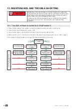
Страница 29: ...28 EN 12 F DG C J J A J J J 12 1 7 B 1 2 0 B 1 2 B 1 0 B 2 84 4 A 2 2 1 2 2 D I 55 9 55 55 9 W 9 9 W OK OK 3 W 2 _A 9_A W W 2 switch and timer 9 9 W 3 OK OK W W OK OK W 4 4 W OK OK W W ...

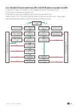
Страница 30: ...29 EN 12 2 Z 7 B 9 9 1 2 0 B 1 2 9 B 1 0 B 2 84 4 A 2 2 1 2 2 D I 55 9 55 9 55 W 9 9 W OK OK 3 3 7 3 W 2 _ 9_ W W 2 switch and timer W 3 OK OK W W W OK OK OK W OK W OK W 4 4 W OK OK W W ...

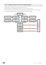
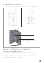
Страница 31: ...30 EN 12 3 Z 7 B 9 9 1 2 0 B 1 2 7 9 B 1 0 B 2 84 4 A 2 2 1 2 2 D I 9 W 9 9 W OK OK 2 switch and timer W W 2 switch and timer 9 9 W 3 OK W OK 4 W OK W ...

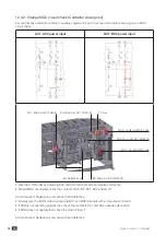
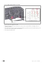
Страница 32: ...31 EN 12 4 12 4 1 F p F Z Z I 9I I 1 I 2 9 9 9 1 1 9 1 1 B 1 7 1 A 2 B 1 7 1 9 9 A 9 2 ...

Страница 33: ...32 EN 12 4 2 G 6 F 1 2 Z Z I 1 I 9_I 7 4 C 9 I _I 7 4 C 9 I 7 C 9 I I 7 4 C 9 B 1 B 2 _A 9_A A F I 2 2 B 9 1 9 9 B 2 B 2 2 F I 2 2 ...

Страница 34: ...33 EN 12 4 3 G 6 F 1 2 Z Z I A I 7 4 C 9 9 A 9 I 7 4 C 9 I B 55 1 B 2 A F I 2 2 B 9 1 9 9 B 2 9 A 9 B 2 F I 2 2 ...

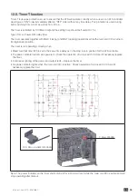
Страница 35: ...34 EN 12 4 4 F c q I COIL POWER 4 I 44 5 3 B 2 D B 2 8 2 1 2 B 2 2 1 W 2 1 2 2 B 1 ...

Страница 36: ...as to ensure that the ATS will operate correctly when a user or an ATS controller 2 55 1 2 9 2 9 1 8 1 D6 2 I 55 8 8 8 its original rest position I B L M 2 B 2 2 the timer B 2 B 8 I 2 2 necessary replace the timer I 7 3 3K I L I 1 2 8 stop operating after timeout ...

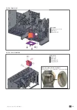
Страница 37: ...36 EN 12 6 Construction of the main components 12 6 1 Parts name C 36 Parts name 4 4 K 3 A 7 C 9 D 9 L 6 K 6 6 6 I 1 2 1 1 ...

Страница 38: ...37 EN 12 6 2 Parts name 3 L6 12 6 3 Parts name L 9 3 36 3 36 _ X x 2 ...

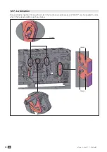
Страница 39: ...38 EN 12 7 X 1 H D G 1 1 ...

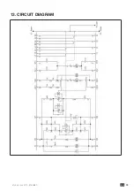
Страница 40: ...39 EN 13 CIRCUIT DIAGRAM ...

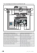
Страница 41: ...4 Protection fusibles 230 Vac 32 A Liaison RJ45 8 8 UNIQUEMENT SUR ATyS C30 F2 F1 F3 F4 Interface déportée ATyS D10 ou D20 UTILISATION A1 A2 CP AC1BC1 AT1 BT1 15 14 13 11 33 31 34 35 B2 B1 CN AC2 BC2 AT2 BT2 ATyS d H Connections on the ATyS C20 30 Terminals I 8 0 7 I 6 9 9 I 8 0 7 I 6 I 7 84 I 6 I I 2 9 9 I I 1 8 I 2 I 1 8 9 9 I 2 3 I 2 6 I 2 6 I I N 8 6 I I 8 55 I 2 I 6 I 2 I 6 I 3 I I 7 ...

Страница 42: ...41 EN ...

Страница 43: ...544 077 C b d 3A SOCOMEC R C S Strasbourg B 548 500 149 B P 60010 1 Rue de Westhouse 67235 Benfeld Cedex France www socomec com ...

Отзывы: