10
3. The battery will take approximately 5 hours to charge. The
battery indicator LEDs will cycle on one by one during the
charging process. Unplug the charger immediately when
all 3 LEDs are illuminated.
m
CAUTION!
FIRE HAZARD. When disconnecting the
charger from the battery, be sure to unplug the charger from
the outlet first, then disconnect the battery from
the charger.
m
WARNING!
This charger does not automatically turn off
when the battery is fully charged. Please take care not to leave
the battery plugged into the charger. Switch off or unplug the
charger at the mains when charging is complete.
4. Timely recharging of the battery will help prolong the
battery's life. Recharge the battery pack when you notice
a drop in the equipment's power.
IMPORTANT! Never allow the battery pack to become fully
discharged as this will cause irreversible damage to the
battery.
Assembly
This cordless pruning saw comes completely assembled
with the guide bar and chain pre-installed. Users simply have
to configure the unit as a hand-held pruning saw or a pole
pruning saw before operation. Follow the instructions below to
connect the machine.
m
CAUTION!
Make sure the battery is not inserted and
the chain are covered by the sheath before assembly.
Hand-held Pruning Saw Assembly
1.
To configure the machine as a hand-held pruning saw, align
the small ridge on the removable battery compartment
with the guide slot on the handle, then slide the removable
battery compartment upward into the handle until it clicks
into position (Fig. 3).
2. Insert the battery into the removable battery compartment
until the push lock buttons click into place (Fig. 4).
Removable battery compartment
Fig. 3
Handle
3. To take the removable battery compartment
off of the
hand-held pruning saw, press the locking button on the
removable battery compartment and slide it out of the
handle (Fig. 5).
Pole Pruning Saw Assembly
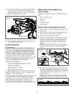
1. To install the pole, align the small ridge on the end of the
pole assembly with the guide slot on the handle, slide the
pruning saw downward into the pole assembly until it clicks
into position (Fig. 6).
Fig. 4
Push lock button
Locking button
Fig. 5
Handle
Pole
assembly
Fig. 6


