background image


21 

Section 4 - ADJUSTMENT & REPAIR 


WARNING 

DO NOT attempt any adjustments, maintenance or 
service with the engine or blades running. STOP 
blades. STOP engine. Set brake. Remove key. 
Remove spark plug wire from spark plug and secure 
wire away from spark plug. Engine and components 
can be extremely hot. Avoid burns by allowing engine 
and components sufficient time to cool. Wear heavy 
leather gloves when handling or working around 
cutting blades. Blades are extremely sharp and can 
cause severe injury. 


4.3.3.  SHIFTER ADJUSTMENT  
 

(Continued from previous page) 

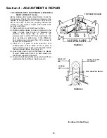
4.  Turn the neutral adjustment nut 1/4 turn clockwise 
to reduce FORWARD creep. Turn the adjustment nut 
1/4 turn counter clockwise to reduce Reverse creep. 
Only turn the adjustment nut in 1/4 turn increments. 
5.  Check for creep in neutral. Start engine. Move 
speed control lever to rear edge of the neutral detent. 
Machine should not move. If further adjustment is 
required, stop engine and repeat Step 4. 


4.3.4. 

TRACTION DRIVE BELT ADJUSTMENT 

Should a gradual loss of traction be noticed, it may be 
necessary to adjust the traction drive belt tension. Adjust 
as follows: 
1.  Move tractor to a firm, level surface. 
2.  Turn engine "OFF". Remove key.  
3.  Remove mowing deck. 
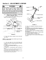
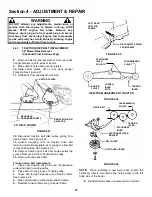
4.  Remove the traction drive belt stationary idler 
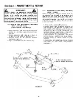
mounting bolt. See Figure 4.11. 
5.  Move the stationary idler one hole towards right side 
of tractor for more belt tension. 


NOTE:  Note the orientation of belt guide and make certain it 
remains in the same orientation after moving idler. Should 
less tension be required move stationary idler towards right 
side of tractor. See Figure 4.11. 

 
6.  Secure stationary idler with mounting bolt. 
7.  Place spark plug wire onto spark plug. Set park 
brake. Start engine. 
8.  Visually inspect traction drive belt for movement. 
When properly adjusted, the traction drive belt should not 
have any movement or rotation with the engine running 
and park brake engaged. 
9.  Should movement be present, readjust traction drive 
belt to release belt tension as described in previous 
instructions. 


FIGURE 4.11 

 
4.4  MOWER BLADE SERVICE 

4.4.1. 

(STANDARD) BLADE WEAR LIMITS 

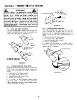
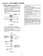
All mower blades should be checked for excessive wear 
and damage before each use. See Figure 4.12. 


FIGURE 4.12 


NEW 
BLADE 

WEAR LIMIT. 
CUTTING EDGE 
WORN. 

DANGEROUS CONDITION! DO 
NOT USE ON MOWER! 

NOTCH FORMING 

MORE TENSION 

BELT GUIDE - MAKE CERTAIN 
BELT GUIDE ORIENTATION IS 
MAINTAINED. 

MOUNTING 
BRACKET 

LESS TENSION 

BELT GUIDE 

STATIONARY IDLER 

STATIONARY IDLER 
MOUNTING BOLT 

MORE TENSION 

LESS TENSION 

MOUNTING BRACKET 

STATIONARY IDLER 

MOUNTING BRACKET 

Содержание WLT160H42GBV

Страница 1: ... Over Head Valve Type Engine H Hydrostatic Transmission Drive System 2 Twin Cylinder Engine 42 42 Cutting Width Mower Deck 48 48 Cutting Width Mower Deck Thank you for buying a SNAPPER product Before operating the Lawn Tractor read and follow the IMPORTANT SAFETY INSTRUCTIONS on pages 2 3 all other instructions contained in this manual and the accompanying booklet About Power Mower Safety Lawn mow...

Страница 2: ...1 DO NOT operate machine on slopes exceeding 15 degrees 27 grade 2 Exercise EXTREME CAUTION on slopes above 10 degrees 18 grade Turn blades OFF when traveling uphill Use a slow speed and avoid sudden or sharp turns 3 DO NOT operate machine back and forth across face of slopes Operate up and down Practice on slopes with blades off 4 AVOID uphill starts If machine stops going uphill or tires lose tr...

Страница 3: ...l light 13 Move joystick if equipped SLOWLY to maintain control during speed and directional changes OPERATION Continued From Previous Column 14 Exercise CAUTION when pulling loads Limit loads to those you can safely control and attach loads to hitch plate as specified with SNAPPER attachment instructions 15 DO NOT operate engine in enclosed areas Engine exhaust gases contain carbon monoxide a dea...

Страница 4: ...ake Lever 14 Deck Lift Mechanism 14 Service Annually 15 Engine 15 Fuel Filter 15 Spark Plug 15 Hydrostatic Transmission Oil 15 SECTION 4 ADJUSTMENTS REPAIR 16 33 Engine Adjustments Repair 16 Mower Deck Component Adjustments 16 Blade Brake Adjustment 16 Blade Belt Adjustment 16 42 Side To Side Deck Level Adjustment 16 42 Front To Rear Deck Level Adjustment 17 48 Side To Side Deck Level Adjustment 1...

Страница 5: ... and Engine Owner s Manual before operating this machine Keep these manuals available for future reference CONTROLS All operators should be acquainted with the operator s controls before attempting start up or operation of the Lawn Tractor See the Control Panel drawing above SPEED CONTROL LEVER CUTTING HEIGHT ADJUSTMENT LEVER LIGHT SWITCH DOWN PARK BRAKE LEVER CLUTCH BRAKE PEDAL OPERATOR S SEAT ST...

Страница 6: ...or surfaces of cutting deck engine and tractor of any accumulation of dirt grass oil etc Keep engine air intake screens and cooling fins clean at all times 2 1 6 With engine OFF move the tractor outside and add fuel to the fuel tank Securely tighten fuel cap after refueling Refer to engine owner s manual for fuel specifications See Figure 2 2 2 1 7 Check Reverse Lockout Mechanism Refer to Section ...

Страница 7: ...URE 2 5 5 Choke engine for cold starting by moving engine speed control to CHOKE position NOTE Some models are equipped with a separate choke control located on the dash of the tractor Pull the control OUT to choke position to start a cold engine Little or no choking will be needed when restarting a warm engine Insert key in switch Turn key to START position to crank engine and hold until engine s...

Страница 8: ...blade See Figure 2 8 FIGURE 2 8 WARNING DO NOT operate blades in reverse STOP BLADES LOOK and SEE behind and down for children pets and hazards before and while backing 2 4 STOPPING ENGINE BLADE WHEEL DRIVE 2 4 1 STOPPING ENGINE 1 Stop engine by turning key to the OFF position See Figure 2 9 FIGURE 2 9 2 4 2 STOPPING WHEEL DRIVE 1 Fully depress clutch brake pedal to stop wheel drive See Figure 2 1...

Страница 9: ...p into slot See Figure 2 12 3 Release pedal FIGURE 2 12 2 4 5 RELEASING PARK BRAKE 1 Fully depress clutch brake pedal Move park brake lever DOWN to release park brake Release clutch brake pedal See Figure 2 13 FIGURE 2 13 2 5 CUTTING HEIGHT ADJUSTMENT 1 Depress lock button on cutting height adjustment lever See Figure 2 14 FIGURE 2 14 2 Raise or lower deck to any of six positions as desired Releas...

Страница 10: ...ntrol all the way in to engage hydro transmission See Figure 2 15 NOTE The transmission will not propel the tractor if it is left in the ROLL position WARNING DO NOT disengage the hydro transmission and coast down slopes DO NOT use Roll Release Control to disengage hydro transmission unless machine motion can be controlled and engine is off ROLL RELEASE CONTROL PULL ROLL RELEASE CONTROL ALL THE WA...

Страница 11: ... until the blade switch is pushed in to the OFF position at which time the system will return to its Reverse Lockout mode This feature should never be selected unless you are absolutely sure that no children or others are present in the mowing area and that all children are away and supervised by a responsible adult 2 7 1 Reverse Lockout Mechanism Override 1 Stop machine Stop blades 2 Depress and ...

Страница 12: ...aced beneath end of oil drain 3 After all oil has drained push drain body IN and rotate clockwise to close 4 Fill engine with new motor oil as specified in engine owner s manual WARNING The following procedure requires the engine and blades to be operated Exercise extreme caution Clear area of loose parts tools first Only operate blades when seated in the operator s seat 3 2 2 CHECK BLADE BRAKE 1 ...

Страница 13: ...f grass clippings and debris d Clean top of deck removing all grass clippings and debris 5 Lubricate spindles with 1 to 3 shots of general purpose grease from grease gun IMPORTANT 48 DECK ONLY Spindles on 48 deck must be kept filled with grease Apply grease from grease gun until grease purges from vent located underneath deck on spindle housing 6 Lubricate all mower deck linkage pivot points with ...

Страница 14: ... of 30 wt motor oil from an oil can See Figure 3 8 FIGURE 3 8 7 Steering Tie Rod Lubricate both ends of steering tie rod with a small amount of 30 wt motor oil from an oil can See Figure 3 9 FIGURE 3 9 8 Park Brake Lever Using 30 wt motor oil lubricate the park brake lever mechanism pivot points which are located on the left hand underside of tractor See Figure 3 10 Lubricate mechanism with a thin...

Страница 15: ...spillage of gasoline 2 Locate fuel filter Remove hose clamps and fuel hoses from both sides of fuel filter 3 Install new fuel filter part number 1 4359 See Figure 3 11 FIGURE 3 11 4 Fill fuel tank with fresh gasoline Refer to engine owner s manual for fuel specifications 3 4 3 SPARK PLUG Remove and replace engine spark plug Refer to engine owner s manual for correct replacement plug and gap specif...

Страница 16: ...ive blade properly replace belt as needed 4 2 3 MOWER DECK ADJUSTMENT LEVELNESS 1 SIDE To SIDE 42 Decks Before making deck leveling adjustments check the tire pressure Check tires and add or release air as needed to bring pressure to 12 PSI in front and 12 PSI in rear tires If tires are properly inflated and mowing is still uneven adjust side to side deck levelness as follows a Place machine on a ...

Страница 17: ...4 Move deck lift lever to 5 position 5 Place a 2 x 4 wooden block on edge under front center of deck 6 Place a 3 x 3 wooden block under rear center of deck 7 Remove hair pins and washers securing sector plates Lower rear of deck onto 3 x 3 block 8 Remove hair pin and washer securing front lift cable to front lift arm See Figure 4 4 FIGURE 4 4 9 Remove front lift cable and rest front of deck onto 2...

Страница 18: ... is within 1 8 from side to side the deck levelness is satisfactory If the difference from side to side is greater than 1 8 continue to next step for adjustment 3 Place a 2 x 4 piece of wood under the front middle portion of deck Place one 2 x 4 piece of wood under the rear of deck on both sides behind the two outside blades See Figure 4 5 4 Lower deck down to rest on the three 2 x 4 pieces of woo...

Страница 19: ...e Add or release air as needed to bring pressure to 12 PSI in front and 12 PSI in rear tires If tires are properly inflated and mowing is still uneven check side to side deck levelness first then proceed to front to rear adjustment Adjust front to rear deck levelness as follows 1 Place machine on a smooth level surface 2 Rotate outside blades so tips are pointed to the front and rear of deck Measu...

Страница 20: ...ed FIGURE 4 8 4 3 2 STEERING ADJUSTMENT Should excessive Play be noted in the steering adjust as follows 1 Turn engine OFF Remove key 2 From left side of tractor locate the steering sector below fuel tank See Figure 4 9 FIGURE 4 9 3 Loosen the eccentric mounting nut and rotate the eccentric clockwise until steering Play is reduced See Figure 4 9 4 Tighten eccentric mounting nut 4 3 3 SHIFTER ADJUS...

Страница 21: ...ine OFF Remove key 3 Remove mowing deck 4 Remove the traction drive belt stationary idler mounting bolt See Figure 4 11 5 Move the stationary idler one hole towards right side of tractor for more belt tension NOTE Note the orientation of belt guide and make certain it remains in the same orientation after moving idler Should less tension be required move stationary idler towards right side of trac...

Страница 22: ...brown Sharpen standard blades as follows 1 Move tractor to a firm level surface 2 Turn engine OFF Remove key 3 Remove mowing deck from tractor 4 Remove mower blade s 5 If a blade is in good condition sharpen cutting edge at an angle of 22 to 28 degrees DO NOT sharpen beyond existing cutting edge Replace blades not in good condition See Figure 4 14 FIGURE 4 14 4 4 4 NINJA BLADE SHARPENING The Ninja...

Страница 23: ...ctor to a firm level surface 2 Turn engine OFF Remove key 3 Remove mowing deck from tractor 4 Position deck on its left side to access blade 5 Remove blade mounting bolts and cone washers See Figure 4 16 FIGURE 4 16 6 Install new blade 7 Torque 30 to 40 ft lbs 4 4 6 48 MOWER BLADE REPLACEMENT 1 Move tractor to a firm level surface 2 Turn engine OFF Remove key 3 Remove mowing deck from tractor 4 Po...

Страница 24: ... garage floor and set the park brake 2 Turn engine OFF Remove key 3 Lower the deck to lowest setting 4 Remove hair pin and washer securing front lift cable to front lift arm See Figure 4 18 5 Remove hair pins from the front deck hanger rod and slide out the rod from deck hanger bracket Front lift arms will be now be disconnected See Figure 4 19 FIGURE 4 18 6 Hold front of deck UP and slide the fro...

Страница 25: ... belt to clear belt guides See Figure 4 23 14 Remove traction drive belt from engine pulley top groove Remove belt from transmission pulley 15 Remove traction drive belt Traction drive belt replacement 1 Place new traction drive belt over transmission pulley and span to engine pulley 2 Place belt into top groove of engine pulley 3 Route belt through stationary and tension idlers See Figure 4 24 4 ...

Страница 26: ...emove key 3 Lower the deck to lowest setting 4 Disconnect the front lift rod assembly from the front hanger bracket See Figure 4 25 5 Remove hair pins from the front deck hanger rod and slide out the rod from deck hanger bracket Front lift arms will be now be disconnected See Figure 4 26 FIGURE 4 25 6 Turn the front wheels to the left 7 Hold front of deck UP and slide the front deck hanger rod to ...

Страница 27: ...w belt to clear belt guides See Figure 4 30 15 Remove traction drive belt from engine pulley top groove Remove belt from transmission pulley 16 Remove traction drive belt Traction drive belt replacement 1 Place new traction drive belt over transmission pulley and span to engine pulley 2 Place belt into top groove of engine pulley 3 Route belt through stationary and tension idlers See Figure 4 31 4...

Страница 28: ...FF Remove key 3 Remove mower deck Refer to Section DECK REMOVAL 4 Remove deck idler tension spring Loosen bolts that secure the end of the spindle pulley covers and rotate cover around out of the way See Figure 4 32 Figure 4 33 FIGURE 4 32 5 Remove old belt 6 Replace with new belt 7 Reinstall both pulley covers 8 Reinstall mower deck to tractor FIGURE 4 33 9 Adjust idler pulley belt guide if neces...

Страница 29: ...LT REMOVAL REPLACEMENT 48 Deck Drive Belt 1 Place tractor on a firm level surface 2 Turn engine OFF Remove key 3 Remove mower deck See Section on DECK REMOVAL 4 Remove deck idler tension spring Remove nuts that secure the spindle pulley covers See Figure 4 35 5 Remove belt 6 Install new belt 7 Reinstall both pulley covers 8 Reinstall mower deck to tractor FIGURE 4 35 ENGINE TO DECK DRIVE BELT PART...

Страница 30: ... fire away from area when charging battery or when handling electrolyte or battery Electrolyte acid is a highly corrosive liquid Wear eye protection Wash affected areas immediately after having eye or skin contact with electrolyte acid Battery acid is corrosive Rinse empty acid containers with water and mutilate before discarding If acid is spilled on battery bench or clothing etc Flush with clear...

Страница 31: ... to 80 charged state 4 With cell caps removed connect battery charger to battery terminals RED to positive and BLACK to negative terminal IMPORTANT 3 16 above cell plates is the recommended level DO NOT place anything in battery other than specified electrolyte 5 Slow charge the battery at 1 amp for 2 hours to bring the battery to full charge 6 After charging check level of electrolyte and add as ...

Страница 32: ...t NOTE The bearing is sealed shielded on one side only The bottom bearing must be installed with the sealed shielded side DOWN 7 Insert spindle shaft up through the bottom bearing Slide spacer down over spindle shaft 8 Install new top bearing Install the top bearing with the seal shield UP 9 Slide circular retaining ring down spindle shaft until it fully locks into groove on shaft 10 Place spindle...

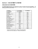
Страница 33: ... 1913 6 1913 Aerator 6 1911 6 1911 Broadcast Spreader 6 1916 6 1916 Lawn Roller 6 1915 6 1915 42 Snow Blade 6 1352 N A 46 Dozer Blade Spring Trip 6 1881 6 1881 Dozer Blade Support Kit 6 1370 6 1370 40 Snow Thrower 6 1880 N A Debris Blower 6 1883 N A RAD Quick Hitch Subframe Kit 6 1879 N A Rear Weight Kit 6 1245 6 1245 Tire Chains 1 6 1399 2 6 1333 6 1333 Ninja Recycling Mulch Kit 6 1987 NA 48 Wave...

Страница 34: ...34 SECTION 5 ELECTRICAL SYSTEM ...

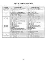
Страница 35: ...E position 2 Move engine speed control to FAST 3 Fuel tank empty 3 Fill with fuel to proper level 4 Engine air pre cleaner and or air cleaner dirty 4 Clean free of all debris 5 Spark plug defective or gap set improperly 5 Service spark plug 6 Fuel filter stopped up 6 Replace fuel filter 7 Water debris or stale fuel in fuel system 7 Drain and clean fuel system Engine Loses 1 Excessive load on engin...

Страница 36: ...ntrol to FAST 4 Forward speed too fast 4 Move speed control to a slower speed 5 Deck side to side level requires adjustment 5 Adjust side to side level 6 Deck front to rear level requires adjustment 6 Adjust front to rear level 7 Cutting Blade dull or damaged 7 Sharpen cutting edges or replace blade 8 Blade belt requires replacement 8 Replace blade belt 9 Blade belt slipping 9 Replace blade belt P...

Страница 37: ...Page 6 X X Drive Belts Check For Wear And Tension Pages 24 29 X X Mower Blades Check Wear Damage And Blade Brake Pages 13 21 23 X Mower Deck Clean Debris Accumulation Page 13 X X X Mower Deck Clean Outside and Underside Page 13 X X X Lubrication Points Grease or Oil Pages 13 14 X X Hydrostatic Trans Oil Check Oil Level Page 15 X Reverse Lockout Mechanism Check Function Page 11 X Change oil every 2...

Страница 38: ...iginal purchase date SNAPPER will not be responsible for any installation cost incurred The battery warranty only covers original equipment batteries and does not cover damage to the battery or machine caused by neglect or abuse destruction by fire explosion freezing overcharging improper maintenance or use of improper electrolyte There is no other express warranty DISCLAIMER OF WARRANTY Implied w...

Страница 39: ...39 PRIMARY MAINTENANCE ...

Страница 40: ...40 PRIMARY MAINTENANCE ...

Страница 41: ...41 PRIMARY MAINTENANCE ...

Страница 42: ...42 PRIMARY MAINTENANCE ...

Страница 43: ..._________________________________________ ___________________________________________________________________ ___________________________________________________________________ ___________________________________________________________________ ___________________________________________________________________ ___________________________________________________________________ __________________...

Страница 44: ...ments If you have any questions about your Snapper product contact your local authorized Snapper dealer or contact Snapper Customer Service at Snapper McDonough GA 30253 Phone 1 800 935 2967 COPYRIGHT 2000 SNAPPER INC ALL RIGHTS RESERVED MANUAL No 7 3621 I R 4 15 00 WARNING ENGINE EXHAUST SOME OF ITS CONSTITUENTS AND CERTAIN VEHICLE COMPONENTS CONTAIN OR EMIT CHEMICALS KNOWN TO THE STATE OF CALIFO...

Отзывы: