background image


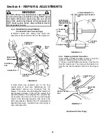
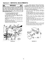
11 

Section 3 – MAINTENANCE 


3.2.2.  CHECK GREASE LEVEL IN TRANSMISSION 
 

(Continued from previous page) 

 
NOTE:  
Do not spill grease or oil on surface of drive 
disc.  See Figure 3.3. 

3.  Reinstall transmission plug. 
4.  Check grease level after each 25 hours of 
operation. 


FIGURE 3.3 


WARNING 

DO NOT attempt any maintenance, adjustments or 
service with engine and blade running. STOP engine 
and blade. Disconnect spark plug wire and secure 
away from spark plug. Engine and components are 
HOT. Avoid serious burns, allow sufficient time for 
all components to cool. Wear heavy leather gloves 
when handling or working around cutting blades. 
Blades are extremely sharp and can cause severe 
injury. 

 
IMPORTANT: DO NOT
 tip machine with carburetor or 
spark plug down. Oil from crankcase will saturate the air 
filter and cause the engine to be hard to start or not start 
at all. If contamination does occur, the air filter will have to 
be replaced. 
 

3.2.3.  CHECK MOWER BLADE  
1.  
Disconnect spark plug wire and secure end 
away from plug. 
2. Tilt mower up on its rear wheels for access to 
the blade cap screw. Do not tilt mower with spark 
plug or carburetor down. See Figure 3.4. 
3. Check torque of blade retaining cap screw. 
Recommended torque should be 40 ft. lbs.  See 
Figure 3.4. 
4.  Check blade for sharpness, wear and damage. 
Refer to Section “Blade Wear Limits”. 


3.2.4.  CHECK ENGINE DRIVE BELT  
1.  
Visually check engine drive belt for cracking, 
fraying, severed or belt strands exposed. If worn or 
damaged, replace belt before operating mower. 
 
3.2.5.  CHECK TRANSMISSION POLY-V BELT 
1.  
Visually check poly-v belt for cracking, fraying, 
severed or belt strands exposed. If worn or 
damaged, replace belt before operating mower. 


FIGURE 3.4 

 
3.3 SERVICE 

ANNUALLY 

Perform all maintenance as described in the “Service 
Schedule” section of this manual. 

3.3.1. Engine 
Service engine according to engine owner’s manual. 
3.3.2. Air 

Filter 

Refer to engine owner’s manual for service instructions. 
3.3.3. Engine 

Oil 

Refer to engine owner’s manual for service 
instructions. 
 

3.4 STORAGE 

PROCEDURE 

Refer to the Engine Owner’s Manual for directions regarding 
engine storage preparations. Prepare the mower for “end of 
season” storage as follows: 

1.  Drain fuel from fuel tank and let engine run until all fuel is 
out of the carburetor. 
2.
  Disconnect and remove the spark plug wire away 
from spark plug before any other preparations are 
made!
 
3.  Tape all openings closed to prevent spraying water into 
exhaust or air intakes during washing. 
4.  Tilt mower up on its rear wheels and thoroughly clean the 
underside of the deck. Do not tilt mower with spark plug or 
carburetor down.  Scrape away any accumulation of grass 
with a putty knife and or wire brush. 
5.  Lubricate all exposed metal with a light coating of oil to 
prevent corrosion.  
6.  On self-propelled models disconnect transfer rod clip and 
remove ground speed control rod before folding handles. 
7.  Loosen handle knobs. Carefully fold the handles forward, 
“flexing” the control cables to prevent cable damage. 
8.  Store the mower in a shed or other dry area, protected 
from weather.  
 

KEEP DRIVE DISC CLEAN ! 

RECOMMENDED 
BLADE RETAINING 
CAP SCREW 
TORQUE VALUE 
SHOULD BE  
40 FT. LBS. 

Содержание EP2167517BV, ERP2167517BV

Страница 1: ...ecycling Model B Briggs Stratton 21 21 Cutting Width V Overhead Valve 675 6 75 HP Engine Horse Power Thank you for buying a SNAPPER Product Before operating your Walk Behind read this manual carefully...

Страница 2: ...extreme CAUTION when changing directions on slopes DO NOT mow steep slopes or other areas where stability or traction is in doubt 3 Use extra care with grass catchers or other attachments these affect...

Страница 3: ...rate engine in enclosed areas Engine exhaust gases contain carbon monoxide a deadly poison MAINTENANCE AND STORAGE 1 DO NOT store mower or fuel container inside where fumes may reach an open flame spa...

Страница 4: ...e 11 Air Filter 11 Engine Oil 11 Storage Procedure 11 SECTION 4 ADJUSTMENTS AND REPAIR 12 18 Mower Blade Replacement 12 Blade Sharpening 12 13 Wheel Drive Control Adjustment 13 Driven and Drive Disc S...

Страница 5: ...URE The nomenclature drawing above Figure 1 1 shows the essential parts of the SNAPPER WALK BEHIND MOWERS It is recommended that all operators of the mower become thoroughly familiar with the controls...

Страница 6: ...p is tightened after refueling Refer to Engine Owners Manual for specifications 2 1 6 Clean exterior surfaces of cutting deck and engine of any accumulation of spilled fuel dirt grass oil etc Keep eng...

Страница 7: ...er nuts on each lower handle as shown in Figure 2 6 FIGURE 2 6 2 Move upper mower handle up or down until the desired position is achieved 3 Tighten the lower nuts on each lower handle to maintain des...

Страница 8: ...mowing slowly If grass is very dense lower each rear wheel latch one notch lower than the front wheel latches to improve recycling performance 2 7 INSTALLATION of GRASS CATCHER Optional accessory on s...

Страница 9: ...ough holes in the side of the deflector See Figure 2 12 FIGURE 2 11 FIGURE 2 12 WARNING DO NOT operate without entire Grass Catcher or guard in place Grass Catcher components are subject to deteriorat...

Страница 10: ...s allow sufficient time for all components to cool 1 Refer to Engine Manual for proper oil specifications and procedures 2 For simplest cleanest oil change loosen lower handle wing nuts and stand mowe...

Страница 11: ...ged replace belt before operating mower 3 2 5 CHECK TRANSMISSION POLY V BELT 1 Visually check poly v belt for cracking fraying severed or belt strands exposed If worn or damaged replace belt before op...

Страница 12: ...See Figure 4 1 4 2 Replace with new blade WARNING DO NOT use a cutting blade that shows signs of excessive wear or damage Refer to Section MOWER BLADE REPLACEMENT for proper blade inspection and serv...

Страница 13: ...f the spring hook and the inside of the clutch cable eye with the wheel drive control released See Figure 4 5 FIGURE 4 5 2 To adjust unhook upper spring from cable eye and rotate spring in direction r...

Страница 14: ...the drive disc or driven disc is causing slippage clean discs as follows 1 Wipe away any oil or grease with a clean cloth 2 Use either an approved grease solvent or hot soapy water to clean drive disc...

Страница 15: ...perators position Then retighten the connector hex nut securely See Figure 4 10 Move ground speed control to the first speed position then back to the sixth speed position Recheck the 1 8 measurement...

Страница 16: ...MPORTANT The bearing on these M series machines is staked into the thrust plate The bearing will have to be driven out with a mallet and a large punch A new bearing with four retaining screws will hav...

Страница 17: ...l new O ring over the outside of the new bearing 6 Install bearing holder and secure with screws 7 Install 3 8 hex lock nut FIGURE 4 14 4 4 BELT SERVICE On self propelled mowers the engine belt transm...

Страница 18: ...worn belt 8 Loop one end of new belt over engine pulley and insert the other end through slot in deck See Figure 4 15 PULLEY POSITION FIGURE 4 16 9 Loop the belt around the pulley on the bottom of th...

Страница 19: ...ts Tighten to proper torque 4 Lumpy or frayed belt 4 Replace belt Mower Will Not Move Or 1 Damaged transmission 1 Contact authorized SNAPPER dealer Loss Of Traction 2 Traction drive belt requires repl...

Страница 20: ...ion Grease Check Grease Level Pages 10 11 X X Periodic Grease Check Pages 10 X Drive Disc Check for Wear Damage Replacement Page 14 18 X Change oil every 25 hours when operating under heavy load or hi...

Страница 21: ...ne air filter To service the filter read and follow the engine operating and maintenance instructions 6 THROTTLE CONTROL Indicates direction to increase engine RPM Hare decrease engine RPM Tortoise an...

Страница 22: ...f the traction control lever Moving the lever toward the handle engages the traction clutch and forward motion starts When the lever is released the clutch disengages and forward motion stops 10 SHIFT...

Страница 23: ...ginal purchase date SNAPPER will not be responsible for any installation cost incurred The battery warranty only covers original equipment batteries and does not cover damage to the battery or machine...

Страница 24: ...ts If you have any questions about your Snapper product contact your local authorized Snapper dealer or contact Snapper Customer Service at Snapper McDonough GA 30253 Phone 1 800 935 2967 COPYRIGHT 20...

Отзывы: