background image

30

Troubleshooting, Adjustment, & Service

Seat Adjustment

The seat can be adjusted forward and back. Move the
lever (A, Figure 33), position the seat as desired, and
release the lever to lock the seat into position.

Battery Charging

A dead battery or one too weak to start the engine may
be the result of a defect in the charging system or other
electrical component.  If there is any doubt about the
cause of the problem, see your dealer. If you need to
replace the battery, follow the steps under Cleaning the
Battery & Cables in the Regular Maintenance Section.

To charge the battery, follow the instructions provided by
the battery charger manufacturer as well as all warnings
included in the safety rules sections of this book.  Charge
the battery until fully charged.  Do not charge at a rate
higher than 10 amps.

Brake Adjustment

This unit does not have a manually adjustable brake.  If
brake does not function properly see your dealer 

WARNING

Keep open flames and sparks away from the
battery; the gasses coming from it are highly
explosive. Ventilate the battery well during
charging.

Figure 33.  Seat Adjustment
A. Seat Adjustment Lever

A

Содержание 1695146

Страница 1: ...T18538 18 5HP CE 20HP Hydro Tractors Mfg No Description 2690688 ELT2044 20HP CE 38 Mower Decks Mfg No Description 1695146 38 Mower Deck CE 44 Mower Decks Mfg No Description 1695147 44 Mower Deck CE LT...

Страница 2: ......

Страница 3: ...13 Starting the Engine 13 Stopping the Tractor Engine 14 Driving the Tractor 14 Mowing 14 Mowing in Reverse 14 Attachment Operation in Reverse 14 Pushing the Tractor by Hand 14 Mower Deck Removal Ins...

Страница 4: ...an explanation of the product s features and controls and maintenance information is included to help you get the most out of your equipment investment Be sure to completely read the Safety Rules and...

Страница 5: ...his equipment safely it is equipped with an operator present safety system Do NOT attempt to alter or bypass the system See your dealer immediately if the system does not pass all the safety interlock...

Страница 6: ...and practical instruction 22 Always wear substantial footwear and trousers Never operate when barefoot or wearing sandals 23 Before using always visually check that the blades and blade hardware are p...

Страница 7: ...loose traction 5 Always keep unit in gear especially when traveling down slopes Do not shift to neutral and coast downhill 6 Avoid starting stopping or turning on a slope If tires lose traction diseng...

Страница 8: ...may ignite Do not spread fuel line clamps further than necessary Ensure clamps grip hoses firmly over the filter after installation 12 Do not use gasoline containing METHANOL gasohol containing more...

Страница 9: ...e Type Spec Engine Model Engine Code Serial Number Mower Deck MFG Number Mower Deck SERIAL Number CE Identification Tag Markings A Manufacturer s Identification Number B Manufacturer s Serial Number C...

Страница 10: ...der in outdoor power equipment manufacturing Although reading this manual and the safety instructions it contains will provide you with the necessary basic knowledge to operate this equipment safely a...

Страница 11: ...er deck do not place hands between mower lift linkage and frame rail 1732070 CAUTION Caution Pinch Point Part No 1732070 44 Mowers Only Caution Pinch Point Part No 1732070 44 50 Mowers Only Pinch Poin...

Страница 12: ...rd to close the choke Headlights The light switch turns the tractor headlights on and off Hour Meter Select Models The hour meter measures the number of hours the key has been in the RUN position Cont...

Страница 13: ...ressing either pedal will increase ground speed Note that the further down the pedal is depressed the faster the tractor will travel Cruise Control The cruise control is used to lock the ground speed...

Страница 14: ...in the left side pod D Figure 2 It can be used to power small electronic devices The accessory must be rated at 9 amps or less Note Operating a 12 volt accessory especially with the engine at idle may...

Страница 15: ...use gasoline containing METHANOL gasohol containing more than 10 ETHANOL gasoline additives or white gas because engine fuel system damage could result SAFETY INTERLOCK SYSTEM TESTS This unit is equip...

Страница 16: ...g the unit will cause transmission damage Do not use another vehicle to push or pull this unit Do not actuate the transmission release valve lever while the engine is running Figure 3 Transmission Rel...

Страница 17: ...tion Slide mower deck under right side of tractor so that mower hitch is aligned with the front tractor hitch 3 Turn wheels straight Lift the mower hanger C Figure 6 Insert rod B through mower hanger...

Страница 18: ...will be increased if it is removed put in a cool dry place and fully charged about once a month If the battery is left in the unit disconnect the negative cable Before starting the unit after it has b...

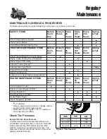
Страница 19: ...ize PSI bar 22 x 10 0 8 10 0 68 20 x 8 0 8 10 0 68 15 x 6 0 6 12 14 0 82 0 96 SAFETY ITEMS Before Each Use Every 5 Hours Every 25 Hours Every 100 Hours Every 250 Hours Spring Fall Check Safety Interlo...

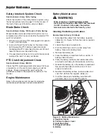
Страница 20: ...Cables B Positive Cables Cover C Hold Down Rod D Wingnut Washer E Battery Safety Interlock System Check Service Interval Every Fall Spring Check the function of the safety interlock system using the t...

Страница 21: ...zel B twisting the socket and bulb clockwise Repeat on other side 4 Close the hood Figure 13 Hood Removal and Installation A Hinge Post B Hood C Pivot Post D Stop A C B Figure 12 Head Light A Socket a...

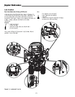
Страница 22: ...made with other parts Keep oil and grease off belts and pulleys Wipe surfaces clean before and after lubrication Grease steering linkage mower linkage rear axle shafts remove wheel hubs front axle piv...

Страница 23: ...jack or chain hoist positioned at the center of the rear frame carefully jack the unit up until the rear tires are approximately 1 2 2 5 5cm off the ground NOTE For overall unit stability during servi...

Страница 24: ...or sharpening use a block of wood to prevent blade rotation while loosening the capscrew 3 Remove the nut C Figure 20 spring washers B and blade Or remove the capscrew D Figure 21 hex washer B spring...

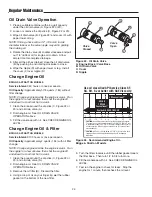
Страница 25: ...ip stick C back into the engine and thread the cap back onto the tube 5 Remove the dip stick and read the oil level The oil level should be between the FULL and ADD marks D If not add oil according to...

Страница 26: ...ned close the oil drain valve B by pushing in and rotating clockwise to close 6 Wipe the nipple D with paper towel or rag Install the cover C over nipple D Change Engine Oil BRIGGS STRATTON MODELS Ser...

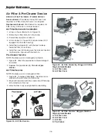
Страница 27: ...with the mesh side up Install the filter C as shown 4 Install the cover B making sure the tabs are inserted into their slots Secure by turning screws clockwise until snug B C D A 1 Pre Cleaner Air Fil...

Страница 28: ...tall the pre cleaner D with the mesh side up Install the filter C as shown 6 Install the cover B making sure the tabs are inserted into their slots Secure with the latch A Pre Cleaner Service NOTE Rep...

Страница 29: ...Plug Resistor Spark Plug Champion RC12YC 1 Stop the engine and allow it to cool 2 See Figures 31or 32 Clean the area around the spark plug 3 Remove the spark plug 4 Check the spark plug gap It should...

Страница 30: ...See your dealer 12 Spark plug s faulty fouled Clean and gap or replace or incorrectly gapped See engine manual 13 Water in fuel Drain fuel refill with fresh fuel Replace fuel filter 14 Gas is old or s...

Страница 31: ...5 Check PTO Electric Clutch See Adjustments Section Adjustment 6 Blades not properly fastened See Servicing the Mower Blades to arbors Engine stalls easily with 1 Engine speed too slow Set to full thr...

Страница 32: ...y follow the steps under Cleaning the Battery Cables in the Regular Maintenance Section To charge the battery follow the instructions provided by the battery charger manufacturer as well as all warnin...

Страница 33: ...indows for an equal amount of tension when the gauge is inserted and removed and make any necessary adjustments by tightening or loosening the adjustment nuts NOTE The actual air gap between the rotor...

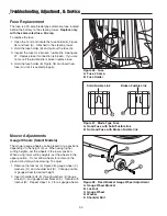
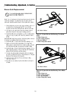
Страница 34: ...Bracket Gauge Wheel Adjustment A Gauge Wheel Bracket B Locknut C Gauge Wheel D Washer E Shoulder Bolt A B C E D Fuse Replacement The fuse is a 20 amp blade type automotive fuse located behind the batt...

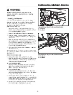
Страница 35: ...re 39 to raise or lower that side of the mower Note The maximum the mower can be adjusted in high cut is 3 8 to 1 2 between the frame and mower up stop See Figure 39 FRONT TO BACK LEVELING 6 Arrange t...

Страница 36: ...the position of all belt guides relative to the belt and pulleys before loosening 4 Some Models Loosen the belt stop bracket s C 5 Remove the old belt and replace with a new belt Make sure V side of b...

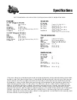
Страница 37: ...er Deck 532 lbs 241 kg NOTE Specifications are correct at time of printing and are subject to change without notice The power ratings for an individual engine model are initially developed by starting...

Страница 38: ...and and torque values are also included For applicable manuals currently available for your model contact our Customer Publications Department at 866 313 6682 Snapper Have the information listed in th...

Страница 39: ......

Страница 40: ...through the summer AERATING YOUR LAWN Consider aerating your lawn in spring Using an aerator to remove cores of soil from the lawn increases the speed of clipping decomposition and encourages deeper r...

Страница 41: ...lch when the grass is wet moist grass does not mulch well and clumps beneath the mower deck Note Always operate the engine at full throttle when mowing PROPER MOWING SPEED ENGINE SPEED GROUND SPEED Al...

Страница 42: ...Snapper INC 535 Macon Street McDonough GA 30253 www snapper com Briggs Stratton Yard Power Products Group Copyright 2006 Briggs Stratton Corporation Milwaukee WI USA All Rights Reserved...

Отзывы: