


6 | SmithsEP.co.uk | Issue 002 - October 2018
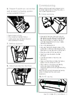
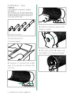
1.
Remove product
from packaging
2.
Remove x 2 screws from each
end of the casing
3.
Slide the casing up from
the chassis
4.
Position heater in
required location
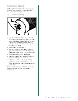
Please note:
When installing a thermostatic radiator valve the
following aspects must be considered to ensure that
the valve performs to its optimum level.
1. The valve should be in a position where it is in
contact with free air circulation within the area
and is not subject to draughts as this will effect
the valve’s performance
2. The valve must not be installed in a position
where the head is likely to be damaged or
where the valve is subject to excessive heat,
either at time of installation or in
operating conditions
3. Ensure that the system is clean and free from
debris and the installation is in accordance with
good plumbing practices
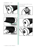
5.
Unscrew both end panels
to access Flow and Return
pipe unions
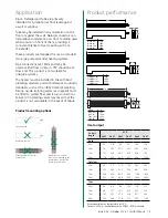
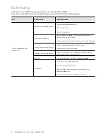
Installation
- Kiosk & Trafalgar
➀
Heat Exchanger
➁
TRV (Thermostatic Radiator Valve)
➂
LSV (Lockshield Valve)
➃
End Panels
➄
Bleed valve
➀
➁
➂
➃
➃
➄
Содержание Kiosk
Страница 18: ...18 SmithsEP co uk Issue 002 October 2018 Notes ...
Страница 19: ...Issue 002 October 2018 SmithsEP co uk 19 Notes ...


