background image

14

Operation

PARTS MANUALS AVAILABLE ONLINE AT smithco.com 

SPRAYER CLEANING

One of the most common causes for faulty-pump performance is corrosion inside the pump. Flush the pump and 

entire system with a solution that will chemically neutralize the liquid pumped. Mix according to manufacturer’s 

directions. This will dissolve most residue remaining in the pump, leaving the inside of the pump clean for the next 

use.

TO PREVENT CORROSION

After cleaning the pump as directed, flush it with a permanent type automobile antifreeze (Prestone, Zerex, etc.) 

containing a rust inhibitor. Use a 50% solution that is, half antifreeze and half water. Then coat the interior of the 

pump with a substance which will prevent corrosion such as Fluid Film or WD40. If unit will not be used for an ex-

tended period of time, disconnect hoses into and out of the pump, seal openings to the pump with caps or tape. 

Dispose of fluids according to all federal, state and local regulations.

All chemicals and chemical residue must be removed after each use.  Dispose of 

fluids and residue according to all federal, state and local regulations.

SPRAYER CLEANING

Empty tank and clean unit thoroughly after each use following these instructions:

  1.  Turn off 3-way valve and rinse inside of tank thoroughly with clean water, remove cap from valve to drain.

  2.  Fill tank ten percent full with clean water, Turn 3-way valve on and start pump and discharge water through 

spray hose or spray boom (with nozzles removed), until empty.

  3.  Turn off 3-way valve again and rinse tank interior thoroughly. Remove 

cap from 3-way valve to drain.

  4.  Rinse exterior of sprayer thoroughly with clean water.
  5.  This sprayer is equipped with a self cleaning strainer. The strainer uses 

the excess pump flow to bypass clogging particles back to the spray 

tank. There is a gap between the tapered inner cylinder and the screen 

face that causes the inlet fluid to flow at a high velocity past the screen 

face providing a continuous wash down of particles. For this wash down 

to occur a minimum of +GPM/23 l/min is required through the bypass 

line.

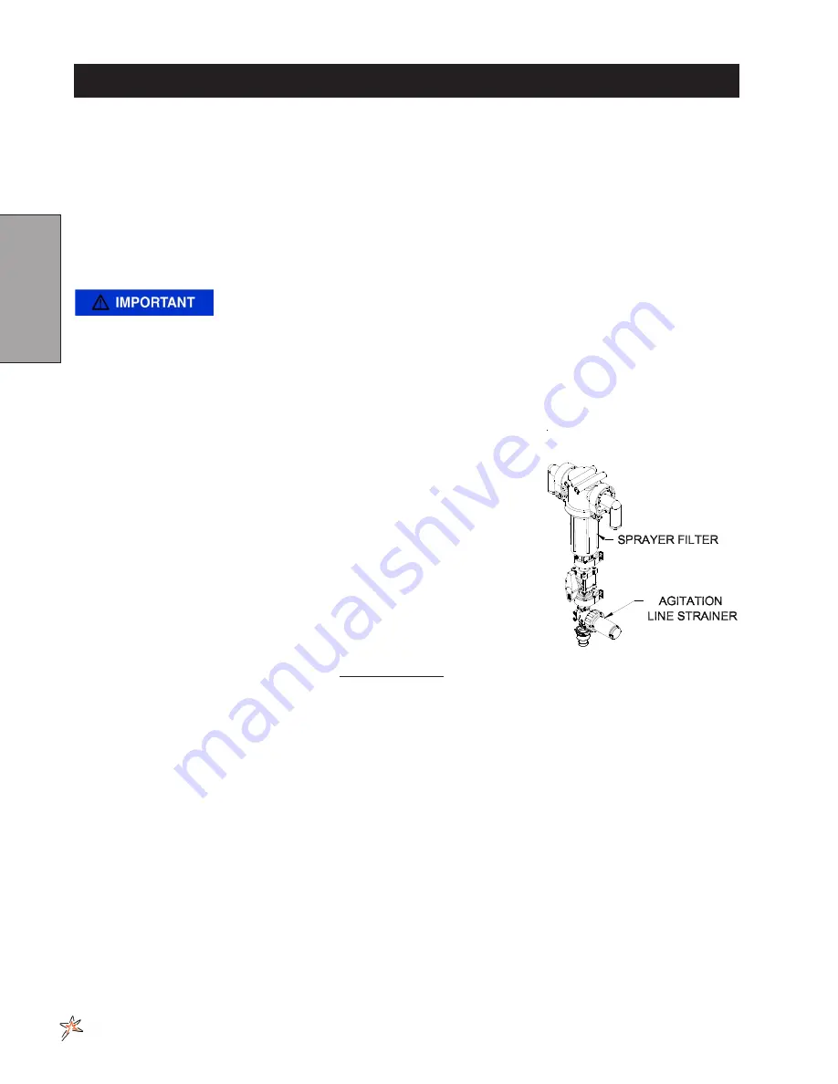
AGITATION LINE STRAINER CLEANING

Agitation line strainer is located below the sprayer filter. This strainer catches 

impurities that go to the turbo-jet agitation system in the spray tank. It has a 

quick disconnect pin on it to remove the bowl. 

After EVERY use

, remove bowl 

and clean screen. Replace screen as needed. We recommend a 50 Mesh 

screen.

MANUAL HOSE REEL

Located at the back of the Spray Star on top of  the tank. Open the ball valve located near the manifold valve  to 

allow fluid to flow into the hose reel. Place the lockout pin in the unlocked position by pulling and turning it half a 

turn, this will allow you to pull out additional hose or to use the handle and wind up the hose. To prevent movement 

during transport or storage place the lockout pin in the locked position.

ELECTRIC HOSE REEL

Located at the back of the Spray Star on top of the tank. Open the ball valve located near the manifold valve to 

allow fluid to flow into the hose reel. To unwind hose just pull on the hose to get the desired amount. To wind up 

the hose make sure the toggle switch is in the ON position, push the momentary push button switch until you have 

reeled in the amount of hose desire. Turn off the safety switch when not in use.

FOAM MARKER SWITCH

Located to the control panel. Use the rocker switch designate to which boom is to be used to dispense foam. Use 

dial located on the foamer to adjust pressure for the amount of foam that will be dispensed. Switch on compressor 

also turns foamer on or off.

1 millimeter (mm) = 0.039 inch
1 centimeter (cm) = 0.393 inch

Содержание Spray Star 5200

Страница 1: ...Star 5200 5220 5224 Radion 8140 5285 5286 Star Commnad II 5287 5288 Star Command I SN 520G001 July 2020 Product Support Hwy SS Poplar Ave Cameron WI 54822 1 800 891 9435 productsupport smithco com Operator s ...

Страница 2: ...ymbols 2 General Safety 3 6 Specifications 7 Optional Spray Equipment 7 Set Up 8 Operation 9 15 Controls Instruments 9 10 Operation 11 12 Tank Agitation 13 Sprayer Cleaning 14 Diagrams 15 17 Main Wiring Diagram 15 Engine Wiring Diagram 16 Hydraulic Diagram 17 Reference 18 Quick Reference 18 TeeJet Spraying App Warranty ...

Страница 3: ...located onthe right main frame below the pump Refer to engine manual for placement of engine serial number For product and accessory information help finding a dealer or to register your product please contact us at www Smithco com Information needed when ordering replacement parts 1 Model Number of machine 2 Serial Number of machine 3 Name and Part Number of part 4 Quantity of parts For easy acce...

Страница 4: ...e Run Engine Oil Water Temperature RPM Gasoline Diesel Glow Plug Hour Meter Hand Throttle Choke Hydraulic Oil Level Ground Speed Park Brake Park Brake Release Fast Slow Lift Arm Moving Parts Pinch Point Hot Surface Hydraulic Fluid Penetration No Riders Rollover Danger Headlamp Blower Warning Danger Caution Seat Belt 20 MAX ...

Страница 5: ...ith the safety messages The appropriate signal word for each has been selected using the following guidelines DANGER Red Indicates an imminently hazardous situa tion that if not avoided will result in death or serious injury This signal word is to be limited to the most extreme situa tions typically for machine components which for functional purposes cannot be guarded WARNING Orange Indicates a p...

Страница 6: ...t decals new decals must be applied New decals are available from your authorized distributor This is a list of decals located on the Spray Star 5200 Part number description and location will help in reor dering a decals A 25 370 Decal 88 dBA B 25 277 Decal Battery Warning C 25 307 Decal Fuel Only D 32 619 Decal Dash Panel E 32 534 Decal Control Panel F 15 463 Decal Spray Pump ...

Страница 7: ...ore storing and always remove the ignition key 11 Disengage all drives and set park brake before starting the engine 12 Never use your hands to search for oil leaks Hydraulic fluid under pressure can penetrate the skin and cause serious injury 13 This machine demands your attention To prevent loss of control or tipping of the vehicle A Use extra caution in backing up the vehicle Ensure area is cle...

Страница 8: ...onents 10 Check hoses for weak or worn condition before each use Make certain that all connections are tight and secure 11 Do not operate unit with leaks frayed kinked hoses or tubing Repair or replace immediately 12 Use only pipe hose and fittings rated for maximum pressure or pressure at which pressure relief valve is set at When replacing pipe hose or fittings use new product 13 Do not operate ...

Страница 9: ...EED Infinitely Variable 0 10 m p h 0 18 kph BATTERY Automotive type 24F 12 volt BCI Group Size 24 Cold Cranking Amps 900 minimum Ground Terminal Polarity Negative Maximum Length 10 25 26 cm Maximum Width 6 88 17 cm Maximum Height 10 25 cm FLUID CAPACITY Crankcase Oil See Engine Manual Fuel 20 gallon 75 7 liters Hydraulic Fluid 10 gallon 37 8 liters Grade of Hydraulic Fluid SAE 10W 40 API Service S...

Страница 10: ...side with Unleaded 87 Octane Gasoline Minimum When filling the fuel tank stop when the fuel reaches 1 inch 2 54cm from the top This space is necessary for fuel expan sion DO NOT OVERFILL Fuel is flammable caution must be used when storing or handling it Do not fill fuel tank while engine is running or an enclosed area fumes are explosive and dangerous to inhale DO NOT SMOKE while filling the fuel ...

Страница 11: ...uge indicates level of fuel in tank H Lights This rocker switch turns lights on by pushing on the top and off by pushing on the bottom Lights are located under front floorboard I Tank Agitation The rocker swithc allows driver to turn on off tank agitation without leaving driver seat J Spray Pump This rocker switch turns the spray pump on by pushing on the top and off by pushing on the bottom The b...

Страница 12: ...quire signal due to the satellites moving significantly from your location This is normal The current draw is extremely low and will have virtually zero impact on a battery s charge Hot start wire should be connected directly to battery 12volts and should remain powered 100 of the time When GPS gauge first receives power the needle will sweep full counter clockwise towards 0 mph Pointer will stay ...

Страница 13: ...sing nuts bolts screws etc and tighten or replace as needed 5 Inspect hydraulic lines for damage or leaks Never use hands to inspect for leaks 6 Check the hydraulic fluid level The hydraulic fluid tank is located under the seat The fluid level should be 2 2 5 6 4 cm from the top of the tank when cold Use only SAE 10W 40 API Service SJ or high er Motor Oil 7 Inspect the steering throttle and shift ...

Страница 14: ... 30 minutes Do not exceed the recommended charging rate If electrolyte starts boiling over decrease charging Always remove grounded battery clamp first and replace it last Avoid hazards by 1 Filling batteries in well ventilated areas 2 Wear eye protection and rubber gloves 3 Avoid breathing fumes when electrolyte is added 4 Avoid spilling or dripping electrolyte Battery Electrolyte is an acidic so...

Страница 15: ...or Agitator Pressure Pressure Output Output Diameter in gpm in L min in psi in bar in gpm in L min 1 8 1 9 7 2 25 1 7 6 3 23 8 1 8 2 7 10 2 50 3 4 10 0 37 9 1 8 3 8 14 4 100 6 9 15 0 56 8 5 32 2 8 10 6 25 1 7 7 6 28 8 5 32 4 2 15 9 50 3 4 12 2 46 2 5 32 5 5 20 8 100 6 9 17 5 66 2 3 16 3 6 13 6 25 1 7 9 1 34 4 3 16 5 6 21 2 50 33 4 14 3 54 1 3 16 7 9 29 9 100 6 9 18 7 70 8 You can change orifice di...

Страница 16: ...r uses the excess pump flow to bypass clogging particles back to the spray tank There is a gap between the tapered inner cylinder and the screen face that causes the inlet fluid to flow at a high velocity past the screen face providing a continuous wash down of particles For this wash down to occur a minimum of GPM 23 l min is required through the bypass line AGITATION LINE STRAINER CLEANING Agita...

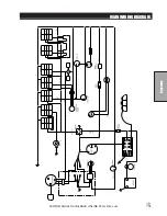
Страница 17: ...15 Diagrams PARTS MANUALS AVAILABLE ONLINE AT smithco com MAIN WIRING DIAGRAM ...

Страница 18: ...16 Diagrams PARTS MANUALS AVAILABLE ONLINE AT smithco com ENGINE WIRING DIAGRAM ...

Страница 19: ...17 Diagrams PARTS MANUALS AVAILABLE ONLINE AT smithco com HYDRAULIC DIAGRAM ...

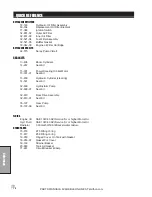
Страница 20: ...14 267 Seal Kit 15 301 Power Steering Orbital Motor 15 301 01 Seal Kit 15 839 Hydraulic Cylinder steering 14 531 Seal Kit 32 609 Hydrostatic Pump 32 609 01 Seal Kit 32 610 Rear Drive Assembly 32 610 01 Seal Kit 76 197 Gear Pump 76 197 08 Seal Kit FLUIDS Engine Oil SAE 10W 40 API Service SJ or higher Motor Oil Hyd Fluid SAE 10W 40 API Service SJ or higher Motor Oil Radiator 3 33Gal 50 50 Antifreeze...

Страница 21: ... you to quickly and easily choose the proper tip for your application Just enter speed spacing and your target rate select your droplet size category and a list of top recommendations is provided SPRAYSELECT TIP SELECTION APP SPRAY SOLUTIONS AT A TOUCH OF A BUTTON DOWNLOAD TODAY ...

Страница 22: ...d the Product as soon as you believe a warrantable condition exists and not later than 30 days from discovery of the condition If you need help locating an Authorized Smithco Distributor or if you have questions regarding your warranty rights or responsibilities you may contact us at Smithco Product Support Department 200 West Poplar Ave Cameron Wisconsin 54822 Telephone 800 891 9435 E Mail Produc...

Страница 23: ...ts through repair or replacement by an authorized Smithco distributor or dealer is the purchaser s sole remedy for any defect This warranty gives you specific legal rights and you may also have other rights which vary from state to state THERE ARE NO OTHER EXPRESS WARRANTIES OTHER THAN THOSE SET FORTH ABOVE ALL IMPLIED WARRANTIES OF MERCHANTABILITY AND FITNESS FOR USE ARE LIMITED TO THE DURATION O...

Отзывы: