background image

11

Service

 OPERATION

Before operating this machine, become familiar with all controls and functions of this unit and the tow vehicle.
Also complete all maintenance requirements and read all safety warnings. By knowing both machines thor-
oughly, how it operates and by doing the prescribed maintenance steps, you can expect relatively trouble-free
operation for years to come.

TOW VEHICLE

You will need a 22HP minimum tow vehicle, with a 2600 lb. minimum load capacity.

1. Clevis Hitch - You will need a 

3

/

4

 diameter  by 4" pin with some type of lock.

2. Ball Hitch - You will need a 2" ball and a locking pin for the coupler.

3. 5th Wheel Hitch - You will need the 5th wheel hitch mechanism mounted on your tow vehicle.

4. After the sweeper is hooked to the tow vehicle, you must raise the jack then turn it so that the foot of the

jack is under the tongue of the sweeper.

DAILY CHECKLIST

1. Check engine oil level. Add as needed. DO NOT OVERFILL.

2. Tire pressure should be 18 psi (1.3 bar) on Sweep Star V62 tires and 20 psi (1.4 bar) on castor wheels.

3. Inspect electrical system for loose connections or frayed wiring, including battery cables. Replace any

faulty equipment or tighten if loose.

4. Check hardware for loose or missing nuts, bolts, screws, etc., and tighten or replace as needed.

5. Inspect hydraulic lines for damage or leaks. Never use hands to inspect leaks.

6. Check hydraulic oil level in right side tank. The level should be 2" to 2

1

/

2

" (5-6.4 cm) from top of tank when

fluid is cold. If level is low, add SAE 10W-40 API Service SJ or higher motor oil.

7. Check controls for smooth, proper working operation. Lubricate as needed.

8. Check and clean all debris from engine compartment.

9. Check coolant tank level. Fill as needed.

STARTING  ENGINE

1. Make sure the fuel flow valve, located on the fuel tank, is “ON.”

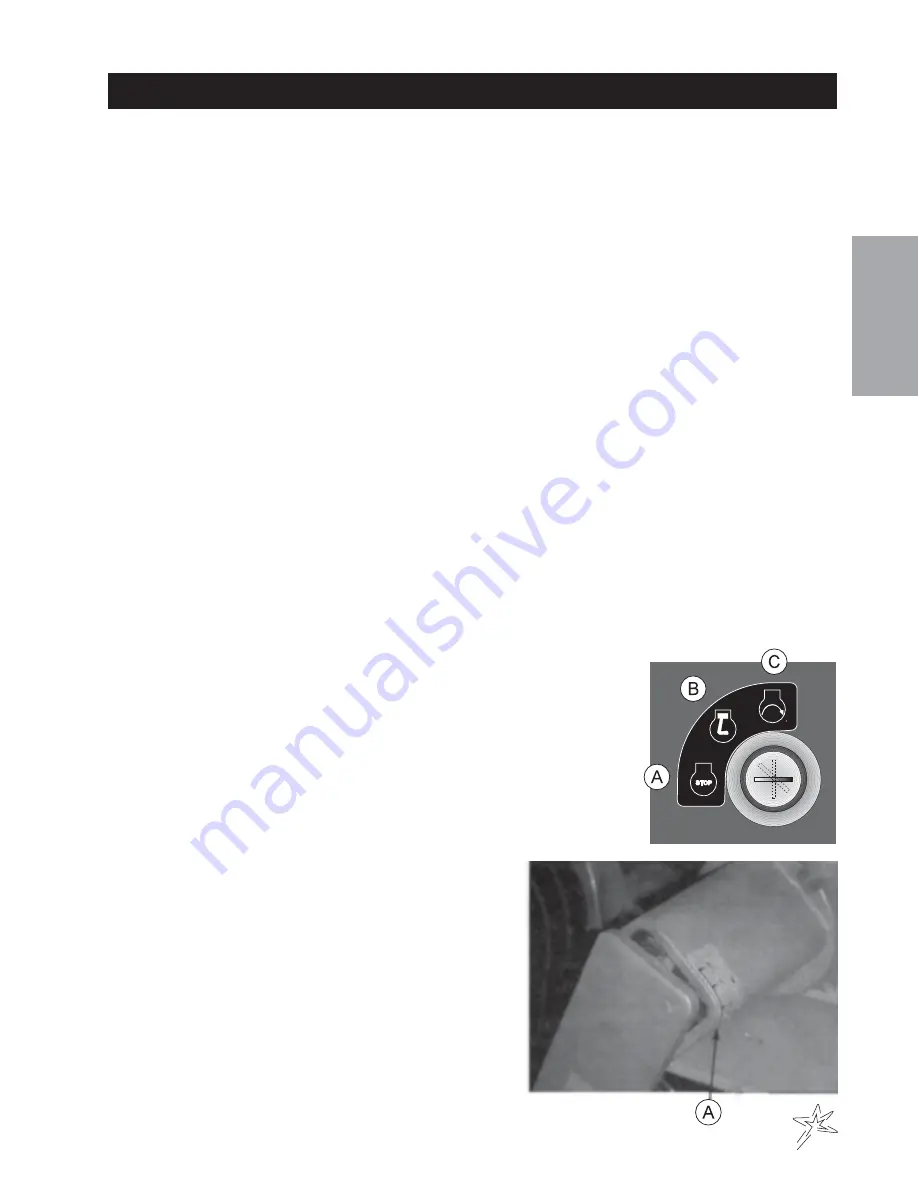
2. The ignition switch is located on remote operator control panel. Insert key

(A) and turn clockwise until engine starts (C). Release key and it will return
to run position (B). Use choke and hand throttle as necessary.

3. Allow engine to idle and warm up a few minutes.

4. Be sure the jack is all the way up and will clear all

ground obstacles.

ADJUSTMENT OF BELT TENSIONER

There are two belt tensioners on the Sweep Star V62. One
controls the tension on the belt from the engine to blower
shaft the other controls the belt on the finger or brush reel.
The proper tension of the idler should be 12 to 15 as per the
gauge (A) on the side of the tightener. Over tightening the belt
will shorten the life of the belt and the machine may not per-
form to the best of its ability. To adjust belt tensioner, loosen
bolt holding tensioner. Bring idler pulley tight to belts and turn
tensioner into belts to 15°. Tighten holder bolt.

Содержание 78-200-B

Страница 1: ...Product Support Hwy SS Poplar Ave Cameron WI 54822 1 800 891 9435 productsupport smithco com Operator s Sweep Star V62 Model 78 200 B November 2007...

Страница 2: ...on 1 Symbols 2 3 Safe Practices 4 Specifications 5 Setup 6 9 Controls Instruments 10 Service 11 13 Operation 11 12 Overloading Debris Hopper and Vacuum Housing Wear 12 Battery 13 Diagrams 14 17 Wiring...

Страница 3: ...ce instructions Failure to do so could result in personal injury or equipment dam age Keep manuals in a safe place after operator and maintenance personnel have read them Right and left sides are from...

Страница 4: ...vel Choke Open Choke Closed Hand Throttle Hour Meter Hour Meter Fuse Glow Plug Glow Plug Off Glow Plug On RPM Gasoline Diesel Water Temperature Temperature Light Engine Oil Engine Stop Engine Start En...

Страница 5: ...Parts Manual Operation Pinch Point Step Hot Surface Hydraulic Fluid Penetration Lift Arm Tractor Engage Disengage PTO Ground Speed Fast Slow H High L Low F Forward R Reverse N Neutral Warning Danger...

Страница 6: ...vehicle A Use extra caution in backing up the vehicle Ensure area is clear B Do not stop or start suddenly on any slope C Reduce speed on slopes and in sharp turns Use caution when changing directions...

Страница 7: ...utomotive type 45 12 volt BCI Group Size 45 Cold CrankingAmps 480 minimum Ground Terminal Polarity Negative Maximum Length 9 23 cm Maximum Width 5 38 14 cm Maximum Height 9 23 cm FLUIDCAPACITY Crankca...

Страница 8: ...behind the hydraulic oil tank This is a negative grounding system Connecting battery cables to the wrong post could result in personal injury and or damage to the electrical sys tem Make sure battery...

Страница 9: ...eper on a level surface Use the jack to raise or lower the front of the sweeper so the tongue is 9 off the ground Position the hitch insert G into the tongue It has two holes the first hole F is for m...

Страница 10: ...en the other adjust ment lock E 6 The control panel M has all the hoses wiring and throttle cable connected to it and to the sweeper The control panel is wrapped and fastened to the front of the sweep...

Страница 11: ...he control panel from the sweeper bring it forward with the hoses to the rear and the throttle on the left hand side 5 Fasten the control panel to the control panel mount H with the four truss head ma...

Страница 12: ...machine operation The hour meter operates when ignition switch is on C Tailgate Lever The tailgate lever is used to open and close the tailgate Refer to decal for direction D Reel Off On Valve Turns t...

Страница 13: ...replace as needed 5 Inspect hydraulic lines for damage or leaks Never use hands to inspect leaks 6 Check hydraulic oil level in right side tank The level should be 2 to 21 2 5 6 4 cm from top of tank...

Страница 14: ...aves and trash 5 They will not hold 7 or 4 cubic yards of aerifier cores 6 The maximum depth in the debris hopper of aerifier cores is Model 78 200 78 500 Sweep Star V62 40 in 101 cm VACUUM HOUSING WE...

Страница 15: ...e is added 4 Avoid spilling or dripping electrolyte Battery Electrolyte is an acidic solution and should be handled with care If electrolyte is splashed on any part of your body flush all contact area...

Страница 16: ...14 Diagrams WIRINGDRAWING...

Страница 17: ...4 13 488 Ignition Switch 1 5 50 359 Oil Light 1 8874 Female Bullet Connector 1 8875 Male Bullet Connector 1 8963 Heat Shrink 2 6 Plug on Engine 1 7 8975 30Amp Circuit Breaker 1 8977 Circuit Breaker Bo...

Страница 18: ...16 Diagrams HYDRAULICDRAWING...

Страница 19: ...8 248 Hydraulic Hose front hyd cyl to rear valve 1 8 78 246 Hydraulic Hose rear hyd cyl to front valve 1 9 13 584 Oil Tank 1 10 8917 12 75 Suction Hose 5 8 ID x 123 4 1 18 040 Hose Clamp 2 11 78 251 H...

Страница 20: ...for the machinery is available from EC Declaration of Incorporation In accordance with EN ISO 17050 1 2004 Smithco Inc 34 West Avenue Wayne PA USA 19087 3311 2006 42 EC The Machinery Directive Sweep...

Страница 21: ...you need help locating an Authorized Smithco Distributor or if you have questions regarding your warranty rights or responsibilities you may contact us at Smithco Product Support Department 200 W Pop...

Страница 22: ...warranty gives you specific legal rights and you may also have other rights which vary from state to state THEREARE NO OTHER EXPRESS WARRANTIES OTHER THAN THOSE SET FORTHABOVE ALLIMPLIED WARRANTIES O...

Отзывы: