


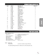


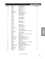


7
Ser
vice
ADJUSTMENTS
WHEEL CREEP
"Creep" is when the engine is running and hydrostatic transmission is in neutral, but due to inadequate align-
ment, wheels still move. Do the following procedure to stop this
motion.
1. Lift up and support machine so rear wheels are off the ground
and can turn freely.
2. In the engine compartment, the hydrostatic transmission is on
the left side. The shift arm (D) is under the pump and comes
out the side. The idler arm (B) has a bearing that runs in the
notch of the shift arm. Loosen bolt (A).
3. With engine running, move bearing (B) so it centers on the
shift arm (D) and 'wheel creep' stops.
4. Tighten all fasteners and test by using foot pedal linkage to
see that 'creep' is removed.
5. Turn engine off and lower machine.
SPRAY PUMP WITH BELT
Located to the right of the engine. The belt should have approximately
1
/
2
" (13mm) of deflection in the center
of the top strand. Loosen and tighten the
3
/
8
-16 x 1
1
/
4
bolts located on the foot of the pump mount.
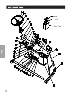
MASTER BOOM SWITCH (FOOT SWITCH)
The master boom switch, located on the left floorboard is used to override the master switch on the computer
console of the spray systems. By pushing down it will turn on/off the booms.
For the TeeJet System
the Mas-
ter Switch on the computer
must be on
for the master boom control switch to work.
GROUND SPEED CONTROL (FOOT SWITCH)
The ground speed control does not work the same as an automotive type cruise. The ground speed control is
located on the center floorboard and is used to lock forward speed.
TO ENGAGE:
1. Flip rocker switch ‘On’ (green light).
2. Obtain desired speed with foot pedal.
3. Step on foot switch to lock speed.
4. Push foot switch again to disengage.
SPRAY BOSS CONTROL - ORANGE
Engages and disengages speed boss. Forward is engage and all the way back is disengage. When the lever
is engaged it sets a stop for the accelerator. The accelerator pedal must be used to maintain this speed. To
adjust speed use the knob on the end of the lever, counter clockwise increases speed and clockwise decreas-
es speed. Disengage the lever and you will have full accelerator pedal range.
TANK AGITATION
The valve to turn on and off the tank agitation is located on the front of the
seat panel, drivers right hand side. Rotate valve handle down to shut off
and rotate back up to turn on..
Содержание 20-700-A
Страница 16: ...14 Diagrams HYDRAULIC DIAGRAM Use dielectric grease on all electrical connections ...
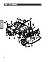
Страница 18: ...16 Diagrams BODY FRAME DRAWING ...
Страница 20: ...18 Parts NOSE CONE DRAWING ...
Страница 22: ...20 Parts NOSE CONE DRAWING ...
Страница 24: ...22 Parts LINKAGE DRAWING ...
Страница 26: ...24 Parts FRONT AXLE DRAWING ...
Страница 28: ...26 Parts OIL AND FUEL TANK DRAWING ...
Страница 30: ...28 Parts SEAT PANEL DRAWING ...
Страница 32: ...30 Parts ENGINE AND PUMPS DRAWING ...
Страница 34: ...32 Parts ENGINE AND PUMPS DRAWING ...
Страница 36: ...34 Parts SPRAY PUMP DRAWING ...
Страница 38: ...36 Parts REAR AXLE DRAWING ...
Страница 40: ...38 Parts SPRAY TANK DRAWING ...
Страница 42: ...40 Parts TURBO QUAD AGITATOR DRAWING ...
Страница 44: ...42 Parts 15 301 ORBITOR DRAWING ...
Страница 48: ...46 Parts 76 638 HYDROSTATIC PUMP DRAWING ...
Страница 50: ...48 Parts 43 116 REAR WHEEL MOTOR DRAWING ...
Страница 58: ...56 Accessories STAR COMMAND I II PLUMBING 15 818 75 Fitting O ring 15 817 50 Fitting O ring ...
Страница 61: ...59 Accessories STAR COMMAND I WIRING 10 638 Fiberglass Cover 10 716 Dynajet Cover ...
Страница 68: ...66 Accessories NOTES ...
Страница 70: ...68 Accessories 17 580 20 HEAVY BOOM ...
Страница 72: ...70 Accessories 17 580 20 BOOM DRAWING ...
Страница 78: ...76 Accessories 17 585 18 HD BOOM DRAWING ...
Страница 80: ...78 Accessories 17 585 18 HD BOOM DRAWING ...
Страница 84: ...82 Accessories 17 601 15 HD BOOM DRAWING ...
Страница 86: ...84 Accessories 17 601 15 HD BOOM DRAWING ...
Страница 96: ...94 Accessories 30 010 ELECTRIC HOSE REEL DRAWING ...
Страница 100: ...98 Accessories HOSE REEL MOUNT DRAWING ...
Страница 102: ...100 Accessories 30 004 FOAM MARKER DRAWING WIRING DRAWING Spray Star 3180 Spray Star 2000 ...
Страница 104: ...102 Accessories FOAMER NOZZLE MOUNT HOSE GUARD MOUNT DRAWING ...
Страница 106: ...104 Accessories 14 291 FOAMER REPLACEMENT PARTS ...
Страница 112: ...110 Accessories 15 620 CHEMICAL CLEAN LOAD PARTS DRAWING ...
Страница 116: ...114 Reference NOTES ...


