COSMOS 302X series servo drives / inverters
Installation, use and maintenance manual - EN
Ver. 1.01
32
5.3.5 Field bus FLxIO
The servo-driver/inverter is equipped with an interface for FLxIO field bus. This bus, based on a RS485 elec-
trical non-insulated interface, performs a reliable, real-time control of complex applications. The connections
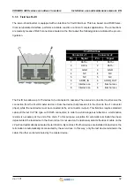
are made by means of RJ45 connectors, situated on the front panel; the following picture indicates the pin con-
figuration.
The FLxIO bus allows up to 15 devices to be connected in cascade. The servo-drive / inverter must receive the
connection from the FLxIO master device or from the device that precedes it in the chain to the J1 connector
(input), while the next device must be connected to the J2 connector (output). This field bus requires standard
cables, Ethernet CAT 5E type, with RJ45 connectors; in order to avoid dangerous reflections, a termination
resistor is necessary at the end of the chain. To this purpose, a solution for automatic termination has been
implemented: the last device in the chain (J2 port is not used on the last slave) detects the lack of cable on the
J2 port and automatically activates the termination. By contrast, if further devices are installed downstream, the
termination is automatically disconnected by the servo-drive. In this way, only the last device terminates the
cable; the other end is terminated by the master device.
J1
J2
FLxIO field bus
Connector J1
Connector J2
Pin
Signal
Pin
Signal
1
DATA+
1
DATA+
2
DATA-
2
DATA-
3
GND
3
GND
4
NC
4
NC
5
NC
5
NC
6
ADDR_IN
6
ADDR_OUT
7
Internal use
7
Internal use
8
Internal use
8
Internal use


