Instructions for the installer
49
12.2 Cable replacement
Should the supply cable need replacing,
remove the back guard by unscrewing the
screws to gain access to the terminal.
Replace the cable. The cable cross-
section must be no less than 1.5 mm² (3 x
1.5).
Make sure that the cables (for the oven or
any hob) follow the best route in order to
avoid any contact with the oven.
WARNING:
The tightening torque of the screws of the terminal supply wires
must be
1.5 - 2 Nm.
12.3 Positioning the oven
Never use the oven door to lever the oven into place when fitting. Avoid exerting
too much pressure on the oven door when open.
We recommend installing the oven with the help of a second person.
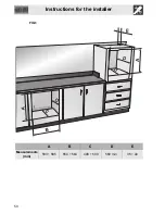
The base on which the oven is resting must be complete as shown in the
illustrations below.
The oven is designed for mounting into any piece of furniture as long as it is
heat-resistant.
Proceed according to the dimensions shown in Figures
1
,
2
and
3
.
For installing under a work top, follow the dimensions given in Figures
1
and
2
.
For installing under a work top with combined cooking hobs, ensure a minimum
clearance from any side walls of at least 110 mm.
When installing in tall units, comply with the dimensions shown in figures
1
and
2
, bearing in mind that the top/rear of the unit must have an opening 35-40 mm
deep.
Remove the screw covers on the frame and screw in the 2 screws
A
(fig. 5) to
fix the appliance to the unit. Replace the screw covers. For installing beneath a
countertop hob, allow for a rear and bottom clearance as shown in Figure
1
(ref.
F
).
See the relevant instructions for fitting and securing the appliance.

