


4 Operation
4-3
4. Operation
4.1 MECHATROLINK-III Communications Settings
This section describes the switch settings necessary for MECHATROLINK-III communications.
4.1.1 Setting Switches S1, S2, and S3
The DIP switch S3 is used to make the settings for MECHATROLINK-III communications.
The station address is set using the rotary switches S1 and S2.
(1) Settings of the Rotary Switches S1 and S2
Set the station address using the rotary switches S1 and S2.
Station Address
S1 S2
00H to 02H: Disabled
(Do not use these addresses.)
0
0 to 2
03H (Factory setting)
0
3
04H
0
4
・
・
・
EFH
E
F
F0H to FFH: Disabled
(Do not use these addresses.)
F
0 to F
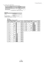
(2) Settings of the DIP Switch S3
The following table shows the settings of the DIP switch (S3).
Switch No.
Function
Setting
Description
Factory setting
Pins 1 and 2
Sets the number of
transmission
bytes.
1
2
Number of transmission
bytes
1: OFF
2: ON
OFF
OFF
16 byte
ON
OFF
32 byte
OFF
ON
48 byte
ON
ON
Reserved. (Do not change.)
Pin 3
Reserved. (Do not change.)
OFF
Pin 4
Reserved. (Do not change.)
OFF
• When using the MECHATROLINK-III standard servo profile, set the number of
transmission bytes to either 32 or 48.
• When using the MECHATROLINK-II-compatible profile, set the number of
transmission bytes to either 16 or 32.
• Turn the power OFF and then ON again to enable the new settings.
Содержание LECYU Series
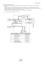
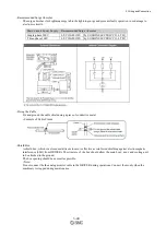
Страница 30: ...1 Outline 1 9 1 4 3 Three phase 200 V LECYU2 V9 Models ...
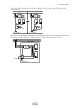
Страница 65: ...3 Wiring and Connection 3 11 3 Wiring Example with DC Power Supply Input DRIVER ...
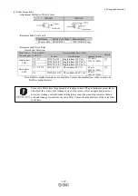
Страница 92: ...3 Wiring and Connection 3 38 External Dimensions Units mm 1 FN Type by Schaffner EMC Inc ...
Страница 93: ...3 Wiring and Connection 3 39 2 FN Type ...
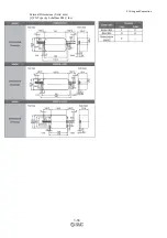
Страница 99: ...3 Wiring and Connection 3 45 4 Cable with Connector for CN8 Model LEC JZ CVSAF External Dimensions Units mm ...
Страница 143: ...4 Operation 4 44 ...


