


96
IMU User Guide revision 3.1 SMC Ship Motion Control www.shipmotion.eu
4.10.4
SETTING CRANE DISTANCE & ANGLE OFFSETS
For the encoders an offset can be entered into the motion sensor. The angle offset information is
entered in position 1 to 5 in the column Angle offset.
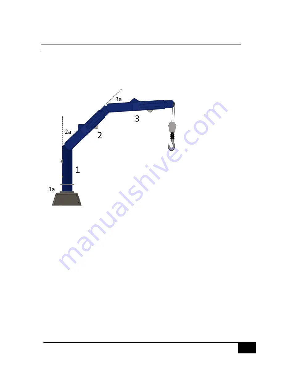
Position 1
The Angle Offset in position 1 sets the angular offset for the yaw encoder marked as 1a in the crane
drawing. Seen from above when the crane is pointing to the fore of the vessel the encoder should
display 0 degrees. When the crane is pointing starboard the encoder should display 90 degrees angle.
When the crane is pointing to the port side the encoder value should be 270 degrees or -90 degrees
if the default clockwise rotation is being used. The offsets are to be used to remove the encoder
offsets from the motion sensor mounting orientation in the fore aft vessel alignment.
In the distance field for position 1 the height of the first node from the crane base is entered, it is
marked as 1 in the below crane image.
Position 2, 3, 4 and 5
For the encoders 2, 3, 4 and 5 the angle is relative to the previous leg of the crane. This means that
when there is no angular difference between the crane leg 2 and 3 the encoder 3 has a 0 angle. The
encoder angles are illustrated as 2a and 3a in the below crane drawing.
Encoder 2, 3, 4 and 5 rotations are seen from the starboard side of the crane. The clockwise rotation
is as default a positive rotation when seeing the crane from this position. Counter clockwise positive
is possible to select by ticking the checkbox for the encoder in the configuration software. I.e. as
default a positive rotation is when the crane arm is being adjusted downwards towards the water


