


!0
i
y
q
y
r
t
i
o
q
t
e
r
w
u
e
w
!1
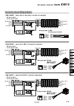
CN0
CN1
CN2
CN3
CN4
CN5
CN6
CN7
0
1
2
3
4
5
6
7
8
9
10
11
12
13
14
15
PWR
0
1
2
3
8
9
10
11
12
13
14
15
4
5
6
7
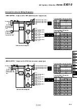
CN1
CN3
CN5
CN7
CN9
CN11
CN13
CN15
CN0
CN2
CN4
CN6
CN8
CN10
CN12
CN14
PWR
1
3
5
7
9
11
13
15
0
1
2
3
4
5
6
7
8
9
10
11
12
13
14
15
0
1
2
3
8
9
10
11
12
13
14
15
4
5
6
7
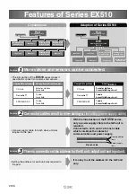
EX510
4
3
2 1
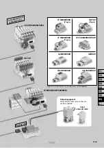
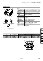
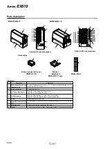
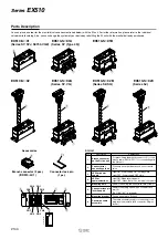
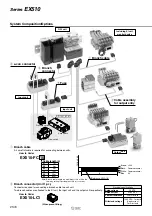
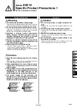
Parts Description
Shown with cover removed.
EX510-DX
1
Shown with cover removed.
EX510-DX
2
Branch connector (2 pcs.)
(
EX510-LC1
)
Accessories
Marker label
Bracket
∗
Attached to
EX510-DX
1
only
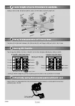
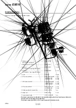
Input Unit
No.
Description
Branch connector on the
input unit side
LED for power supply
LED for display
Fuse
e-con connector
Mounting hole
Mounting groove for DIN
rail
Cover
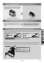
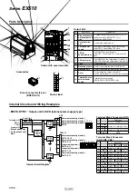
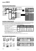
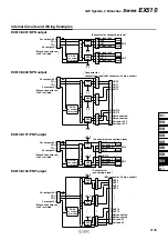
Applications
1
2
3
4
5
6
7
8
For press-fitting the branch connector (
o
) to the branch cable (EX510-FC
) for
connecting with the GW unit.
Light ON: Power supply ON (Normal) state
Light OFF: Power supply OFF state
Light ON: When the input for sensor signal is turned ON.
Light OFF: When the input for sensor signal is turned OFF.
For attaching to a DIN rail or when mounting with screws to an accessory bracket
(
!0
).
Used for mounting the unit with two M4 screws.
For protecting the sensor cables. Place a marker label (
!1
) on the top of the body.
Replaceable fuse (EX9-FU10)
Connecting sensor, etc.
Series
EX510
2136


