SMC Networks EX500 Series Скачать руководство пользователя страница 3

2

3

SAFETY

The body of unit and this manual contain the essential information for the protection of
users and others from possible injury and property damage and to ensure correct
handling.
Please check that you fully understand the definitions of the following messages
( symbols ) before going on to read the body of this manual, and always follow the
instructions. 
Please also read the instruction manuals etc. of related machines and equipments and
understand the contents before use.
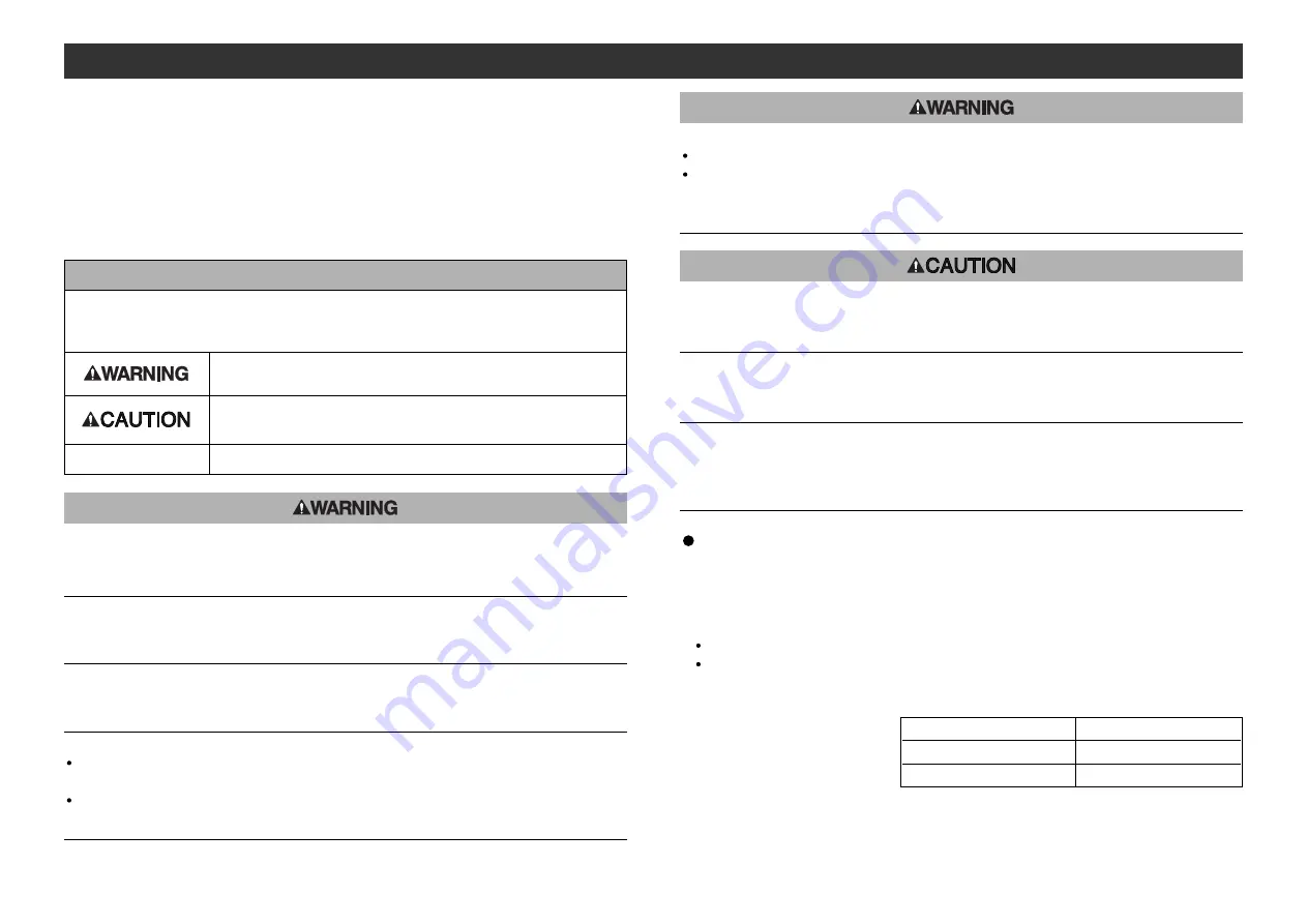
IMPORTANT MESSAGES

Indicates a potentially hazardous situation that could result in
death or severe injury if you do not follow instructions.

Read this manual and follow its instructions. Signal words such as WARNING,
CAUTION and NOTE will be followed by important safety information that must be
carefully reviewed.

Indicates a potentially hazardous situation that, if not avoided,
may result in minor injury or moderate injury. 

Gives you helpful information.

NOTE

Do not disassemble, 
modify ( including modification of printed circuit board ) or repair.

Otherwise injury or failure can result.

Do not operate beyond specification range.

Otherwise fire, malfunction or damage to the reduced wiring system can result.
Confirm the specifications before operation.

Do not operate in atmosphere of flammable/explosive/corrosive gas.

Otherwise fire, explosion or corrosion can result.
This reduced wiring system is not explosion-proof type.

For use in interlock circuit:

Provide double interlock system by adding different type of protection

( such as mechanical protection ). 

Check that the interlock circuit is working normally.

Otherwise accident caused by malfunction can result.

Before performing maintenance:

Turn off power supply.
Stop air supply, exhaust compressed air in piping, and confirm the release to
atmosphere. 

Otherwise injury can result.

Conduct proper functional inspection after completing maintenance.

In the case of abnormality such as unit does not work normally, stop the operation.
Otherwise safety cannot be assured due to unintended malfunction.

Avoid mixing of CC-Link dedicated high-performance cable and other cables (
CC-Link dedicated cable and/or Version 1.10 compatible CC-Link dedicated
cable ).

Mixing can hinder normal data transmission and cause trouble.

Provide grounding to improve safety and noise resistance of reduced wiring sys-
tem.

Provide grounding as close to the unit as possible to shorten distance for grounding.

1. UL508-compatible limited voltage/current circuit

A circuit using the secondary coil of an insulating transformer that meets following condi-

tions as power source.

Maximum voltage ( at no load ): 30Vrms ( 42.4Vpeak ) or below

Maximum current:

( 1 ) 8A or less ( including when short-circuited )

( 2 ) When limited by the circuit protector ( such as fuse )

having the following rating.

2. UL1310-compatible Class 2 power supply unit or circuit of max. 30Vrms ( 42.4Vpeak ) or

less using a UL1585-compatible Class 2 transformer as power source. ( Class 2 circuit )

No-Load Voltage ( Vpeak )

Max. Current Rating ( A )

0 to 20 [V]

5.0

Above 20 [V] to 30 [V]

100/peak voltage

Handling precautions

Use the following UL-recognized DC power supply to combine with.

Содержание EX500 Series

Страница 1: ...Reduced wiring system EX500 GMJ1 Instruction Manual CC Link Compatible GW Unit URL http www smcworld com EX OMI0026...

Страница 2: ...pecification 24 Display 25 Input Unit Manifold Part Names 26 Dimensions 27 Installation 28 Specification 29 Wiring 30 Display 31 EX9 Series General Purpose Output Block Part Names 32 Dimensions 33 Mou...

Страница 3: ...system by adding different type of protection such as mechanical protection Check that the interlock circuit is working normally Otherwise accident caused by malfunction can result Before performing...

Страница 4: ...ace near power cable Do not operate the product in a place where there is a source of surge Use a surge absorbing element built in type to directly drive the load that generates surge voltage such as...

Страница 5: ...d valve for input devices such as sensor and for controlling GW SI by using power supply connector cable Note1 Display the power supply status and communication status with PLC Note2 Station number sw...

Страница 6: ...branch total extended length 10m or less Number of stations occupied Station type 3 stations Remote device station Transmission speed 156kbps 625kbps 2 5Mbps 5Mbps 10Mbps Cable length between stations...

Страница 7: ...this EX500 is the terminal of CC Link connection connect the terminal resistor Refer to Connection of terminal resistor page 12 in this manual Avoid the mixing of CC Link dedicated high performance c...

Страница 8: ...Gray Wiring continued Power supply wiring Connect the power supply connector cable to the power supply connector of GW unit There are two types of cables different in connector shape straight type and...

Страница 9: ...nnector Power supply connector 1 3 4 5 2 1 3 4 5 2 A Two power supply system B Single power supply system Branch wiring wiring to communication ports For wiring with solenoid valves or input devices c...

Страница 10: ...unit for SV VQC series Connector C1 0 Branch cable with M12 connector Connector C2 1 Input unit manifold Manifold valve with SI unit for SV VQC series Terminal plug NOTE When no Input unit is connecte...

Страница 11: ...has no received data Lights on COM D is receiving data Lights off COM D has no received data Display Description NOTE When connecting manifold valve only without connecting Input unit manifold LEDs o...

Страница 12: ...ate solenoid valves relays etc in combination with EX9 series general purpose output block For how to use it refer to section EX9 Series General Purpose Output Block page 32 in this manual SI unit for...

Страница 13: ...dually Note 1 For mounting installation methods of solenoid valve manifold etc refer to the catalogs instruction manuals technical data etc of each valve series When connecting general purpose output...

Страница 14: ...alve series Cassette Tie rod 40 50 63 80 100 125 Series Manifold Inner diameter of applicable cylinder tube mm Max 8 stations Single solenoid valve General purpose output block EX500 Q 02 only Max 16...

Страница 15: ...ector 5 Connects with sensor Note1 Indicator LED 6 Indicates sensor signal status Note2 Marker 7 To be used for writing input No etc End block 8 Completes the end of Input unit manifold DIN rail 9 To...

Страница 16: ...2 3 4 5 6 7 8 Specification Specifications for Input unit Connected block Current source type input block PNP input block or Current sink type input block NPN input block Connected block stations Max...

Страница 17: ...onnecting sensors confirm the specification of output signal carefully Otherwise malfunction can result The key position for mounting sensor connector is as shown to the right Consider this key positi...

Страница 18: ...eries SI unit for VQC series EX500 Q 02 Output connector 1 Connects with output device Note1 Indicator LED 2 Indicates the output status Note2 Part name No Application Note1 For wiring method refer to...

Страница 19: ...f output block stations 1 2 3 4 5 6 7 8 The above dimensions indicate when one unit of power block width 21mm is combined For details refer to the instruction manuals technical data etc of EX9 series...

Страница 20: ...output devices DC24V Power supply for output devices DC24V 2 Power supply for output devices 0V Power supply for output devices 0V 3 4 5 Power supply for sensor DC24V Power supply for sensor 0V Groun...

Страница 21: ...is unused If this terminal plug is not used COM LED of GW unit does not light on EX500 AC000 S How to order 1 7 6 5 4 3 2 8 M12 16 44 7 Plug Connector Pin Layout Waterproof cap Mounted on unused ports...

Страница 22: ...to the branch of unlit COM port and the branch cable with M12 connector is connected to the Input unit When connecting no Input unit connect a terminal plug Item No Solution Corrective action PWR LED...

Отзывы: