13 - 46
13. POSITIONING MODE
13.4.3 Basic setting of signals and parameters
Create programs in advance using set up software(MR Configurator2
TM
). (Refer to sections 13.4.2, and 13.9.)
(1) Parameter
(a) Command mode selection (parameter No. PE01)
Make sure that the absolute value command system has been selected as shown below.
Absolute value command system (initial value)
Parameter No. PE01
0
(b) ST1 coordinate system selection (parameter No. PA14)
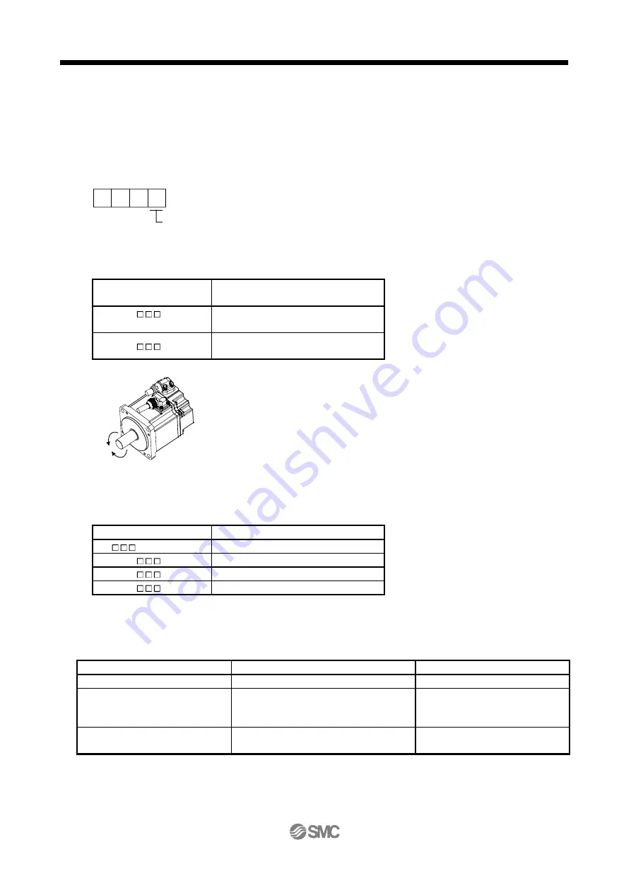
Select the servo motor rotation direction at the time when the forward rotation start (ST1) turns ON.
Parameter No. PA14 setting
Servo motor rotation direction when forward
rotation start (ST1) is turned on
0
(initial value)
CCW rotation with + position data
CW rotation with - position data
1
CW rotation with + position data
CCW rotation with - position data
CW
CCW
(c) Feed length multiplication (parameter No. PE02)
Set the feed length multiplication (STM) of position data.
Parameter No. PE02 setting
Position data input range [mm]
0 (initial value)
-999.999 to +999.999
1
-9999.99 to +9999.99
2
-99999.9 to +99999.9
3
-999999 to +999999
(2) Signals
Choosing the program using DI0 to DI2 and turning ON ST1 performs positioning operation according to
the set program. At this time, reverse rotation start (ST2) is invalid.
Item
Setting method
Description
Selection of program operation mode
Automatic/manual selection (MD0)
Turn MD0 ON.
Program selection
Point table No./Program No. selection 1 (DI0)
Point table No./Program No. selection 2 (DI1)
Point table No./Program No. selection 3 (DI2)
Refer to section 13.2.3.(1).
Start
Forward rotation start (ST1)
Turn ON ST1 to start the program
operation


