background image

SG361 GSM/GPRS Module 

SG361 GSM/GPRS Module                  Version 1.0                    2014-02-23                Page 6 of 8


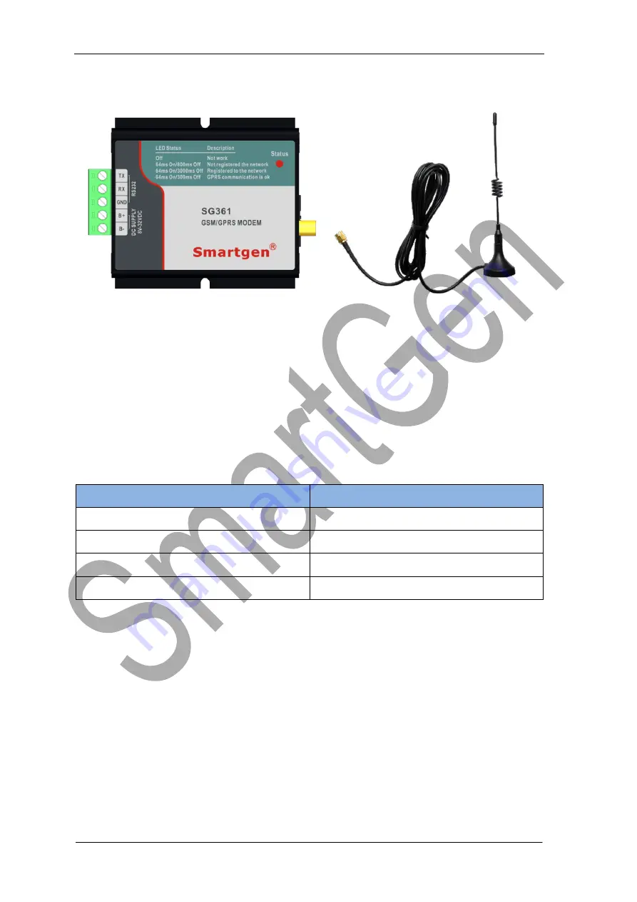
2.2   STRUCTURE   


1

 TERMINAL 

TX

: 

Sending end; connect to RX of RS232 interface. 

RX

: 

Receiving end; connect to TX of RS232 interface. 

GND

Ground wire; connect to ground wire of RS232 interface. 

B+

: 

Positive power supply; voltage range: (8~32)V 

B-

: 

Negative power supply 

2

 NETWORK STATUS INDICATOR (RED) 

LED STATUS 

DESCRIPTION 

Off 

Not work 

64ms On/800ms Off   

Not registered to the network 

64ms On/3000ms Off 

Registered to the network 

64ms On/300ms Off 

GPRS communication is ok. 

3

 SIM CARD SLOT 

Drawer type card slot, used for installing the SIM card 

4

 ANTENNA INTERFACE 

Fit with standard SMA interface and 50

Ω matching impedance.   

Connect 

the 

antenna 

to 

SMA 

interface 

and 

then 

tighten the screws. 


Содержание SG361

Страница 1: ...SG361 GSM GPRS Module USER MANUAL Smartgen Technology...

Страница 2: ...smartgen cn All rights reserved No part of this publication may be reproduced in any material form including photocopying or storing in any medium by electronic means or other without the written per...

Страница 3: ...ule Version 1 0 2014 02 23 Page 3 of 8 Contents 1 OVERVIEW 4 2 PRODUCT FEATURE 5 2 1 TECHNICAL PARAMETERS 5 2 2 STRUCTURE 6 3 TYPICAL APPLICATION AND INSTALLATION STEPS 7 3 1 TYPICAL APPLICATION 7 3 2...

Страница 4: ...SG361 GSM GPRS Module SG361 GSM GPRS Module Version 1 0 2014 02 23 Page 4 of 8 1 OVERVIEW SG361 GSM GPRS Module has SMS Short Message Service function and GPRS data transmission function...

Страница 5: ...via AT command GPRS multi slot class 10 8 GPRS mobile station class B GPRS class 10 maximum 85 6 kbps downstream rate SMS text mode PDU mode Antenna Interface 50 SMA Female SIM card 1 8 3V Automatic...

Страница 6: ...wer supply voltage range 8 32 V B Negative power supply 2 NETWORK STATUS INDICATOR RED LED STATUS DESCRIPTION Off Not work 64ms On 800ms Off Not registered to the network 64ms On 3000ms Off Registered...

Страница 7: ...lot and then close the drawer 2 INSTALL ANTENNA Connect the antenna to SMA interface and then tighten the screws 3 COMMUNICATE WITH CONTROLLER Details connection way pleases refer to Chapter 3 1 TYPIC...

Страница 8: ...S Module SG361 GSM GPRS Module Version 1 0 2014 02 23 Page 8 of 8 3 3 INSTALLATION It is fixed by two M3 screws when installed and the center distance is 61 5mm The overall dimensions please refers to...

Отзывы: