background image

Chapter 2

Installing and using the SMART OPS PC module

smarttech.com/kb/171747

8

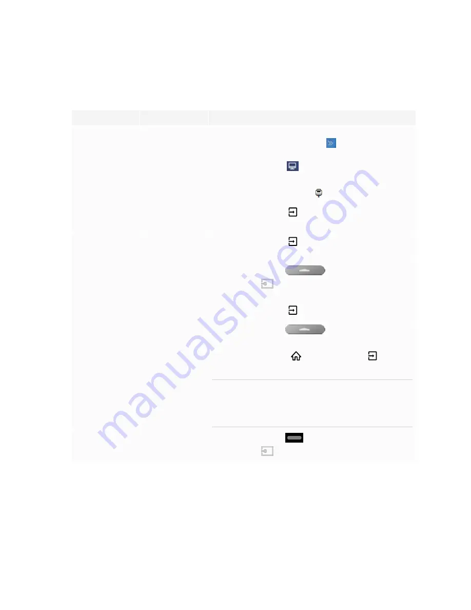
Viewing the OPS PC module input source

1. Open the display’s input source menu:

Display series

iQ status

Procedure

GX

N/A

Open the

Side Toolbar

menu by tapping and sliding either

of the Side Toolbar menu handles

(located on either side

of the screen) towards the center of the screen, and then tap

the

Input Source

icon

.

OR

Press the

Input Source

button

on the remote control.

MX100

N/A

Press the

Input

button

on the front control panel or the

remote control.

MX (V2)

MX (V2) Pro

Enabled or
disabled

Press the

Input

button

on the front control panel or the

remote control.

6000S

6000S Pro

7000R

7000R Pro

Enabled

Tap the

Home

button

below the screen, and

then tap

Input

.

OR

Press the

Input

button

on the remote control.

6000S

6000S Pro

7000R

7000R Pro

Disabled

Tap the

Home

button

below the screen.

OR

Press the

Home

button

or the

Input

button

on the

remote control.

TIP

If you want the OPS PC module’s input source to appear
whenever you wake up the display, tap the star in the
upper-left corner of the OPS PC module’s thumbnail.

7000-V2

7000-V2 Pro

Enabled or
disabled

Tap the

Home

button

at the bottom of the screen, and

then tap

Input

.

2. Select the OPS PC module input source.

Содержание PCM11-1

Страница 1: ...Was this document helpful smarttech com docfeedback 171747 SMART OPS PC modules with Windows 10 Pro USER GUIDE PCM11 i5 PCM11 1 PCM11 i7v PCM11 2 PCM8 i5 PCM8 1 PCM8 i7v PCM8 2...

Страница 2: ...demarks of SMART Technologies ULC in the U S and or other countries Microsoft and Windows are either registered trademarks or trademarks of Microsoft Corporation in the United States and or other coun...

Страница 3: ...ance could void the user s authority to operate this equipment Restriction Operations in the 5 15 5 25GHz band are restricted to indoor usage only IEEE 802 11b or 802 11g operation of this product in...

Страница 4: ...o agr s Son fonctionnement est soumis aux deux conditions suivantes 1 Le dispositif ne doit pas produire de brouillage pr judiciable et 2 Ce dispositif doit accepter tout brouillage re u y compris un...

Страница 5: ...wing the OPS PC module input source 8 Connecting USB drives peripherals and other devices 9 Connecting external displays 10 Chapter 3 Troubleshooting 11 Appendix A Connectors 12 PCM11 series 12 PCM8 s...

Страница 6: ...lation at your fingertips without the need for an external device or additional cables Install familiar Windows software applications such as SMART Notebook collaborative learning software SMART TeamW...

Страница 7: ...smarttech com kb 171544 You can then view the OPS PC module s input on the display CAUTION Do not install or remove the OPS PC module while the display is turned on Ensure the power switch on the bac...

Страница 8: ...mote control MX V2 MX V2 Pro Enabled or disabled Press the Input button on the front control panel or the remote control 6000S 6000S Pro 7000R 7000R Pro Enabled Tap the Home button below the screen an...

Страница 9: ...g those devices to the OPS PC module s USB 2 0 Type A USB 3 0 Type A and USB Type C receptacles PCM11 series PCM8 series Alternatively you can connect USB devices to the USB receptacles on the display...

Страница 10: ...external displays You can connect an external display to the HDMI out connector on the OPS PC module rather than the HDMI out connector on the display This allows you to duplicate or extend the OPS PC...

Страница 11: ...rd c Enable Use the On Screen Keyboard For more information see Use the On Screen Keyboard OSK to type l Enable tablet mode Tap the notification icon in the bottom right corner of the screen and then...

Страница 12: ...the connectors on the PCM11 series of SMART OPS PC modules No Connector Connects to Notes 1 Stereo 3 5 mm Headphones or headsets See Analog audio cables and connectors 2 HDMI in External video source...

Страница 13: ...ives peripherals and other devices See Connecting USB drives peripherals and other devices on page 9 and USB cables and connectors 6 RJ45 N A The OPS PC module uses the SMART Board interactive display...

Страница 14: ...es and connectors 2 USB 2 0 Type A 2 Supported USB drives peripherals and other devices See Connecting USB drives peripherals and other devices on page 9 and USB cables and connectors 3 USB 3 0 Type A...

Страница 15: ...to Notes 5 HDMI out External display See Connecting external displays on page 10 and HDMI cables and connectors 6 Stereo 3 5 mm out External speakers or headphones See Analog audio cables and connecto...

Страница 16: ...ries contain substances that can be harmful to the environment and to human health The crossed out wheeled bin symbol indicates that products should be disposed of in the appropriate recycling stream...

Страница 17: ...SMART TECHNOLOGIES smarttech com support smarttech com contactsupport smarttech com kb 171747...

Отзывы: