

April 15, 2008
Rev C
April 15, 2008
Rev C
April 15, 2008
Rev C
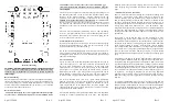
Reference Drawing
CAUTION: The PowerExpander Pro ONLY regulates power to the
receiver. Whatever input voltage comes in on the Deans Ultra Plug
connectors goes straight to the servos. You may need to regulate the
input voltage.
Receiver Mounting
The receiver mounts in the center of the unit. 3M dual-lock mounting
tape has been supplied to mount the receiver. This tape’s holding power
is extremely strong so it is recommended that the whole 1”x2” piece not
be used. Instead it is recommended that you cut some 1”x ½” strips and
use these on either end of the receiver.
Receiver Connections
CAUTION: Do not plug any receiver pigtails into the battery input
of your receiver. On PCM it will put your receiver into DSC mode,
on a 2.4GHz receivers it may cause your receiver to unbind. All
connections from the PowerExpander are meant to ONLY plug into
servo outputs.
The receiver servo outputs are connected to the pigtails coming out of
the PowerExpander Pro in the area marked “Channel Inputs From
Receiver” on the reference drawing. The two channels on the end
(“Chan A” and “Chan J”) have power connections to the receiver
in
addition to the signal connection for that channel
. It is recommended
that if you have a receiver that has less than ten channels that you still
use both the end connections as this will provide you with power
redundancy to the receiver in event that a power or ground lead should
fail.
The unit will accommodate end-loading receivers and top-loading
receivers. All signals from the receiver into the PowerExpander Pro are
RF filtered. This prevents noise from the servos from going out the
receiver connectors into the receiver.
Connections Directly To Receiver
If you want to connect a device directly to the receiver instead of going
through the PowerExpander Pro, make sure the current draw of the
receiver and the device is less than one amp.
We do not recommend plugging any servos directly into the receiver.
They can draw too much current, even analog servos. Devices that may
be plugged directly into the receiver are the Smart-Fly Ignition Cutoff
and some smoke pumps.
Servo Connections
Servos are connected to the PowerExpander Pro along the two rails on
either side of the receiver. The servo connectors are universal in that
they will work with Futaba or JR connectors. When using a JR
connector please be careful to observe the polarity of the connection.
The negative servo power lead (black on Futaba, brown on JR) is
indicated by the “minus” sign. The positive servo power lead (red on
Futaba and JR) is indicated by the “plus” sign. The servo signal line
(white on Futaba, orange on JR) is indicated by the “top hat” symbol.
All receiver channels have each servo signal output individually
buffered. If a servo were to short out its signal wire, the other servos on
that channel would not be affected. Eight of the channels have three
servo outputs and two of the channels have four servo outputs. The
channels with four servo outputs correspond to Futaba’s and JR’s
assignments of the rudder channel.
The unit also RF filters each signal output and matches line impedance
resulting in a cleaner signal down long servo leads. The impedance
matching reduces the electrical “ringing” that can occur on long servo
leads. Ringing can generate RF interference and can reduce receiver
range.
“Smart-Sense” Power Connections
Power is connected to the unit through the two Deans UltraPlug male
connectors. The polarity of the Deans connector is shown on the
reference drawing. The “Smart-Sense” power inputs will show, by the
LED for that input being lit, that the input connector is enabled. When
an input is enabled, the voltage drop into the unit is less than 0.15V at
five amps and less than 0.3V at ten amps. This is much less than a diode
voltage drop, which most other units use. The Smart-Sense” input
recognizes this by the fact the two input sources are within 20 millivolts
of each other. When the LED for an input is not lit that input is turned
off and power cannot flow out of the connector, as would be the case if a
pack shorted.
If one LED is not lit then the power on that connector may have
something wrong with it. This could be one of several things. If you
have batteries connected directly to the unit then the two packs may not
be charged to the same level. The higher pack will be drawn from until
the two packs equalize in voltage. After the pack voltages equalize
power will be drawn from both batteries. If one pack has lost a cell and
is at a much lower voltage this equalization will never happen and the
power to the system will come from the good pack. If a pack should
short, that input will be disabled and the system will run off the good
pack.
If regulators are being used on the two inputs then one regulator may be
set more than 20 millivolts below the regulator that has the LED lit or
the regulator may have gone bad. The “Smart-Sense” inputs can be used
to get dual regulators in the “neighborhood” of being equal but it should
be remembered that regulators will not draw evenly when their outputs
are connected together, unless they are matched to less than a hundredth
of a volt which is very hard to do and may be impossible for a given set
of regulators. One thing to remember if you are using adjustable
regulators and one battery pack is going down faster than the other,
adjust the voltage up of the regulator on the battery pack that is being
used less.
It is highly recommended that you beef up the power wiring between
the battery and the PowerExpander Pro above the standard 22ga wiring.
Failure to do this will diminish the effectiveness of the PowerExpander
Pro at providing the highest possible voltage to the servos. Servos
operating at lower voltages produce less torque than they are rated at.


