


SI-700 –EIA-232/EIA-485 Interface
2
Interface Settings
There is two interface settings located on the front panel to adapt this interface to the applications:
EIA-232 Mode and EIA-485 Bus Terminator.
-
EIA-232 Mode: Half-Duplex/Full-Duplex
The EIA-232 Mode setting adapts the use of EIA-232/EIA-485 Interface to the communication driver
at the EIA-232 side. Normally interfaces of this type connect unidirectional buses with a bi-directional
bus. The unidirectional bus will be able to present the Full Duplex features caused by transmission
message reflection (echo). If the driver used does not treat properly the reception and the
transmissions messages simultaneously, either disabling the reception or discarding the reflected
message, it will be necessary to select the Half-Duplex option. If the reflected message does not
disturb the applications, you can select the Full-Duplex option.
-
EIA-485 Bus Terminator: On/Off
The EIA-485 is a Multi-Drop type bus. The transmitter driver is put in the high impedance (Hi-Z) state
when there is no message to transmit. Therefore, the EIA-485 bus requires a bus terminator to
prevent noise problems during the idle state of the EIA-485.
For the proper line impedance matching it is necessary to activate only one terminator by bus. Leave
the other terminators deactivated.
Connectors
There are two connectors on the front panel to interconnect two communication systems. The first,
an RJ12 type connector is used for the EIA-232 systems and the other, a terminal block type
connector is used for the EIA-485 systems.
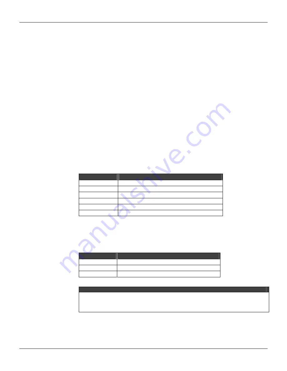
RJ12 Pin Assignment
Pin Number
Description
1
Connected to 6 pin.
2
Not used
3
RxD: EIA-232 input signal - reception
4
TxD: EIA-232 output signal - transmission
5
GND: EIA-232 signal ground
6
Connected to 1 pin
Note:
Pins 1 and 6 are interconnected to allow the handshaking between the modem signals when
required by communication drivers, such as Clear-To-Send (CTS) with Request-To-Send (RTS)
interconnection.
Pin Block Terminal
Pin Number
Description
1
+: EIA-485 Non inverting signal
2
-: EIA-485 Inverting Signal
3
GND: Reference for EIA-485 Communication Signal.
NOTE
The GND pin is used to set up a voltage reference for all EIA-485 nodes, on the same bus. The
EIA-485 side of EIA-232/EIA-485 Interface is isolated and is left in a floating state. To avoid
undesirable high common mode voltage it is recommended to make all of the EIA-485 nodes on
the same voltage reference by connecting all GND pins and grounding at just one point.
Содержание SI-700-EIA-232
Страница 8: ...SI 700 EIA 232 EIA 485 Interface A 2...