Stand-alone grid inverter
Sunny Island 2012/2224
Technical Description
SI2012_2224-TEN082311 | 98-2005110 | Version 1.1
EN
Страница 1: ...Stand alone grid inverter Sunny Island 2012 2224 Technical Description SI2012_2224 TEN082311 98 2005110 Version 1 1 EN...
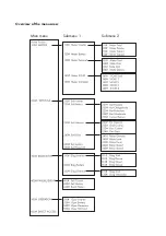
Страница 2: ...Overview of the menu area Main menu Submenu 1 Submenu 2...
Страница 3: ...and 2012 2224 18 4 1 2 Sunny Remote Control 1 19 4 2 Name Plate Firmware Version 20 4 2 1 Sunny Island 2012 2224 20 4 2 2 Sunny Remote Control 1 21 5 Installation 22 5 1 Required Tools and Resources 2...
Страница 4: ...C2 Gen Grid 50 7 4 Sunny Remote Control 1 51 7 5 Communication 53 7 5 1 Communication with Sunny Island 53 7 5 2 Communication With External Devices 56 7 6 Additional Connections 59 7 6 1 Battery Temp...
Страница 5: ...ff 87 10 1 4 Disconnecting the Device from Voltage Sources 87 10 1 5 Restarting the System after Automatic Shutdown 88 10 2 Navigation Area 89 10 2 1 Standard View 1 92 10 2 2 Standard View 2 93 10 2...
Страница 6: ...20 12 2 Start Options 121 12 3 Charge State SOC and SOH 121 12 4 Charge Control 122 12 4 1 Boost Charge 124 12 4 2 Full Charge 124 12 4 3 Equalization Charge 126 12 4 4 Manual Equalization Charge 127...
Страница 7: ...ower Adjustment 149 13 2 8 Operation Together With Sunny Boys 150 13 3 Generator and Grid 151 14 Relay 152 15 Sunny Boy in the Island Grid System 154 15 1 Setting the Stand alone Grid Parameters 154 1...
Страница 8: ...ent During Startup 184 18 4 Display of Failures and Events 184 18 5 Events 185 18 6 Error Categories 188 18 7 Warnings and Failure messages 188 18 8 Troubleshooting 192 19 Optional Devices 195 19 1 Ex...
Страница 9: ...application described in this documentation The use of a stand alone grid system to power life sustaining medical devices is not permitted The Sunny Reomet Control 1 is suited only for installation i...
Страница 10: ...e of the tasks described in this document must be performed only by qualified electricians and are labeled accordingly with warnings 1 3 Storage of the Documentation The manuals for the stand alone gr...
Страница 11: ...y warning about a condition which can lead to property damage if the warning is ignored Information Notice designates information which is important for the optimal operation of the product Menu Menu...
Страница 12: ...e used to set up stand alone power supply systems with outputs of up to 9 kW Automatic Generator Control Thanks to its sophisticated generator management it can control connected diesel generators in...
Страница 13: ...tion allows quick access to all important data even while the system is running The Sunny Island can be controlled easily with the Sunny Remote Control 1 SRC 1 external display An MMC SD card provides...
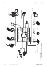
Страница 14: ...Sunny WebBox Loads DC DC Charger Fuel Cell Battery Generator Public grid POWE R SYST EM REPO RT MEMO RY SMAC OM NETC OM USBC OM Battery temperature sensor Description Control voltage DC supply contact...
Страница 15: ...SMA Solar Technology AG SystemOverview Technical Description SI2012_2224 TEN082311 15 1 phasig 1 phasig parallel 3 phasig...
Страница 16: ...personal hazard DANGER Risk of lethal electric shock when opening the devices Installation and repair of the devices in the stand alone grid system must be carried out exclusively by qualified personn...
Страница 17: ...and the devices for any signs of damage Ensure that all parts are included in the delivery see section 4 1 Scope of delivery Page 18 If something is missing or if the devices have been damaged during...
Страница 18: ...lements are included A 1 Sunny Island 2012 2224 and lid B 1 Wall bracket C 1 Battery temperature sensor D 2 3 pin print terminals for connecting relays 1 2 E 2 4 pole print terminals for connecting ba...
Страница 19: ...echnical Description SI2012_2224 TEN082311 19 4 1 2 Sunny Remote Control 1 The following elements are included A 1 Sunny Remote Control 1 SRC 1 B 2 Screws and dowels C 1 CAT5e FTP patch cables 2 x RJ4...
Страница 20: ...ou can identify the Sunny Island by the type plate and firmware version The following diagram shows the type plate of the Sunny Island 2224 The name plate is located outside on the right side of the h...
Страница 21: ...ology AG Unpacking Technical Description SI2012_2224 TEN082311 21 4 2 2 Sunny Remote Control 1 You can identify the display by the name plate The type plate is located on the rear side of the Sunny Re...
Страница 22: ...in delivery Stripping pliers Drill e g stone drill 6 to 10 mm Drill Crimping tool for cable lug Torque wrench 4 Nm to 10 Nm 13 mm socket wrench 4 mm allen wrench Cable knife Ratchet including extensi...
Страница 23: ...olar Technology AG Installation Technical Description SI2012_2224 TEN082311 23 5 2 Sunny Island 2012 2224 5 2 1 Dimensions Housing Heat shrink tubing Material not included in delivery 470 mm 445 mm 18...
Страница 24: ...performance In domestic installations the unit should not be mounted on plasterboard walls or similar materials in order to avoid audible vibrations The Sunny Island can make noises when in use that...
Страница 25: ...ntee sufficient heat dissipation All external cables are connected through the underside of the housing This requires a minimum clearance of at least 50 cm Direction Minimum clearance sides 10 cm abov...
Страница 26: ...backward inclination of at most 15 Do not mount the device with a forward inclination Do not mount the device lying flat on its back Mount the device at eye level NOTICE Short circuit due to condensat...
Страница 27: ...sed When mounting onto a wall use at least two of the horizontal holes and the lowest one in the middle When mounting onto a post use at least three of the holes in the middle use the superior one in...
Страница 28: ...ice onto the wall bracket with its attachment plate somewhat displaced to the left The right edge of the back side of the device must be flush with the right edge of the wall bracket Transporting the...
Страница 29: ...eck on both sides to see that the device sits correctly 5 Secure the enclosure so it cannot be accidentally lifted up Shove the Sunny Island toward the right on the wall bracket until it snaps into pl...
Страница 30: ...heft protection Protect the device against theft Secure the Sunny Island with a lock onto the wall mounting bracket The lock must meet the following specifications Size A 6 mm 10 mm in diameter B 21 m...
Страница 31: ...play you can control the Sunny Island and with it the island grid system Choose a solid fundament for mounting Protect the Sunny Remote Control 1 from dust wet conditions corrosive substances and vapo...
Страница 32: ...sing the Sunny Remote Control s mounting plate To do this unscrew and remove the mounting plate from the back of the Sunny Remote Control 3 Draw the position of the holes to be drilled 4 Install the d...
Страница 33: ...ith insulated tools exclusively 3 Use protective clothing and eyewear when working on the battery 4 During normal operation it is not possible to accidentally touch the electrolyte Do not damage the e...
Страница 34: ...sured in the vicinity of the battery Therefore a safety distance must be observed in the form of an air clearance in which no sparks or smoldering materials are allowed The clearance distance is calcu...
Страница 35: ...hich may be used in the system unless the battery manufacturer has determined other values Consult the appropriate battery manufacturer for other battery type values Maximal charging voltage in V cell...
Страница 36: ...in Enclosure lid Only remove the lower enclosure lid from the Sunny Island when you want to mount install or maintain it A upper enclosure cover B lower enclosure cover C control area DANGER Risk of l...
Страница 37: ...le from the inner side of the enclosure cover in the new devices the cable is not in place 4 Keep the cover in a safe place NOTICE The components in the Sunny Island e g communications interface can b...
Страница 38: ...see chapter 7 Sunny Island Electrical Connection Page 39 2 Plug the cable for the control area into the lower enclosure cover 3 Starting from the front place the cover evenly on the housing 4 Screw a...
Страница 39: ...Install line safety switches max 25 A before the Sunny Island as seen from the grid side Follow every safety notice in this chapter during installation NOTICE The components in the Sunny Island e g c...
Страница 40: ...overview of all connections of the Sunny Island A DC connections B Additional protective earth conductor C Additional connection terminals battery current sensor battery temperature sensor etc D Commu...
Страница 41: ...etric thread cable screw connections guarantee a dust free and waterproof installation of the cables in the housing and also provide strain relief for the cable connection Close all unused openings in...
Страница 42: ...connections are provided in the following sections DC connection Chapter 7 2 DC connection Page 43 AC connection Chapter 7 3 AC Connection Page 46 Grounding Chapter 7 3 1 Grounding Page 47 Sunny Remo...
Страница 43: ...ternal DC fuse Install an external DC fuse between the Sunny Island and the battery as a protective conductor Dimension the fuse in proportion to the cable cross section used Sunny Island 2012 fuse NH...
Страница 44: ...all installation work on the island grid system WARNING Danger of burns or even death due to arcing and short circuiting when connecting the battery All safety and maintenance instructions provided b...
Страница 45: ...ctions in the following sequence 1 Remove the protective insulation from each DC cable 2 Fit the bare cable ends with ringed cable lugs 3 Introduce the DC cables into the enclosure from below and to t...
Страница 46: ...of 6 mm for the AC installation The nominal AC current is 9 6 A Information The sub distribution unit must be equipped with appropriate circuit breakers Be sure to observe all the applicable regional...
Страница 47: ...DC connection area Proceed as follows 1 Strip the protective conductor 2 Fit the protective conductor with a ringed cable lug max cross section 50 mm 3 Screw the ringed cable lug onto the enclosure s...
Страница 48: ...ed cable screw joint on the right of the enclosure s underside 2 Insert the 3 conductor cable through the threaded joint 3 Draw the cable into the enclosure 4 Flip the AC1 s terminal connectors N and...
Страница 49: ...ed and the PE cable is installed firmly 7 Connect the N and L cables according to the labeling on the AC1 terminal connectors L and N must not be swapped 8 Tighten the cable screw joint s lock nut fir...
Страница 50: ...1 to phase L2 and slave 2 to phase L3 This circuitry results in a right rotating field If a phase fails within a three phase grid the cluster continues to run In order to protect your loads you may re...
Страница 51: ...hase L1 slave 1 to phase L2 and slave 2 to phase L3 This circuitry results in a right rotating field The system does not monitor additional fuses Check any additional fuses regularly NOTICE The compon...
Страница 52: ...enings to the Display socket on the conductor board 4 Install all communication leads see chapter 7 5 Communication Page 53 before you reassemble the rubber element and refit it onto the Sunny Island...
Страница 53: ...on the Installation 1 Lay the communication cable separately from the AC cables 2 DO NOT feed the communication leads through the membranes with their plugs mounted Feeding the plugs through the memb...
Страница 54: ...nny Island Remove the terminator from the SyncIn socket Plug the RJ45 plug of the communication cable from the master device in the SyncIn socket of the slave 1 The plug snaps audibly into place If no...
Страница 55: ...the slave 2 The plug snaps audibly into place Plug a terminator in the SyncOut socket of the slave 2 The terminator snaps audibly into place 3 Install all communication leads before you reassemble th...
Страница 56: ...ails on the required cable type Which of the Sunny Island s connections are used Whether or not the communications cables must be terminated Whether the PE needs to be connected to the cable shield Yo...
Страница 57: ...t and reinsert it into the opening on the floor of the Sunny Island 5 Fit any unused openings on the enclosure with blind seals 6 Connect the other end of the communication cable to the communication...
Страница 58: ...at different transmission rates 1200 to 19200 bps to communicate with external devices The parameter 250 06 ComBaud must be set correspondingly The Sunny Island uses the SMA Net protocol for communica...
Страница 59: ...s to an insufficient charge of the battery in the long run In this case the Sunny Island s display shows a warning Replace the defective battery temperature sensor promptly Always operate the Sunny Is...
Страница 60: ...with wire sleeves 3 Introduce both cables from the outside through the opening 4 Plug one wire into each of the BatTmp contacts of the 4 pole terminal included 5 Tighten the screws of the contact 6 I...
Страница 61: ...l DC generators or DC loads to the island grid system In this operating situation the Sunny Island s internal current measurement works imprecisely the charge state of the battery is not determined ex...
Страница 62: ...attery current sensor which is connected to the Sunny Island 1 must be connected to the terminal BatCur see following diagram If the battery current sensor is connected as described above positive bat...
Страница 63: ...th the parameters 241 01 Rly1Op and 241 02 Rly2Op see chapter 14 Relay Page 152 Commissioning the Battery Temperature Sensor When connecting the battery temperature sensor set up the internal offset o...
Страница 64: ...t operation contact NO Normally opened opened in standby 7 Insert the plug into the appropriate socket on the board Operating principles of the relays The relays are changeover contacts they can be us...
Страница 65: ...orts generators that can be started and stopped by a single contact and generators that require more than one contact in combination with the optionally available generator manager GenMan NOTICE If a...
Страница 66: ...d tool 2 Fit the cables with wire sleeves 3 Introduce both cables from the outside through the opening 4 Plug one wire into each of the BatVtgOut contacts of the 4 pole terminal included 5 Tighten the...
Страница 67: ...ol 2 Fit the cables with wire sleeves 3 Introduce both cables from the outside through the opening 4 Plug one wire into each of the DigIn contacts of the 4 pole terminal included 5 Tighten the screws...
Страница 68: ...m Each Sunny Island must be configured with the aid of the rotary code switch Upon delivery this rotary code switch is set to 0 The rotary code switch is found on the back of the back of the display o...
Страница 69: ...been laid so as to be strain relieved 3 Are there no communication cables inside the Sunny Island which are touching a stripped 230 V wire 4 Are all cable conduits on the Sunny Island sealed 5 Have al...
Страница 70: ...nal display 8 1 Sunny Island 8 1 1 Control Panel on the Enclosure The following diagram describes the elements of the control panel 8 1 2 Control Panel Buttons The Sunny Island s control panel has thr...
Страница 71: ...The following table describes the meanings of the color signals from the battery LED Green Red Orange Operating mode of the Sunny Island Off device has been switched off ON Standby no inverter operati...
Страница 72: ...mote Control 1 You can navigate the Sunny Island s menus with the external display Sunny Remote Control 1 The Sunny Remote Control 1 consists of Display Key rotating pushbutton Information The Sunny I...
Страница 73: ...es off again see also chapter 18 1 Error Confirmation Page 184 1 Row Uhrzeit in hh mm ss 2 Row grid or generator power in kW TotExtPwrAt ggf Pfeil in Energieflussrichtung z B Einspeiseleistung PV Gene...
Страница 74: ...cancel function Select value Confirm entry Answers yes no Starts the device hold down the button while on standby Stops the device hold down the button during operation Operation of the Sunny Island w...
Страница 75: ...e that all electrical connections have the correct polarity and make sure that everything is connected according to the instructions in chapters 7 Sunny Island Electrical Connection Page 39 Always sav...
Страница 76: ...tically Reasonable operation is possible this way with little manipulation 1 Insert the NH fuse in the BatFuse or close the BatFuse s DC disconnector 2 Start the Sunny Island Press the DC start key on...
Страница 77: ...accidentally accessed the QCG and would only like to restart the system New Battery if you would like to change the main battery settings but retain the system configuration New System if you would li...
Страница 78: ...figuration 003 01 selection see Overview of System Configurations Page 79 presetting is 1phase 1SI a Voltage Frequency type 003 02 AcVtgFrqSet 230V_50Hz 220V_60Hz Date 003 03 Dt dd mm yyyy Time 003 04...
Страница 79: ...I 3 phase system 3 Sunny Islands 8 After entering the parameters the following message appears on the display Init Device OK START 9 Confirm the question Press and hold the pushbutton on the Sunny Rem...
Страница 80: ...ormation in section 18 Troubleshooting Problem Solving Page 184 Parameter Lists Further details concerning the modifiable parameters are found in chapter 17 Parameter List Overview Page 160 Note that...
Страница 81: ...60 mV Only after activation of the parameter with 50 mV or 60 mV will other parameters 02 03 and 04 in the menu 225 Battery Current Sensor be shown and activated Set the maximal current for the batter...
Страница 82: ...inal clamp 2 again Make sure the wires have the correct polarity BatCur to terminal clamp 1 BatCur to terminal clamp 2 11 Start the Sunny Island see chapter 10 1 1 Switching On Starting Page 83 12 Che...
Страница 83: ...on the Sunny Island During the start procedure the inverter LED goes from orange to green 4 Let go of the start stop button The inverter LED glows green continually The Sunny Island is in operation W...
Страница 84: ...it for the following displays to finish 4 To init system hold Enter is displayed after the startup phase 5 If you want to go into the QCG press and hold the Sunny Remote Control 1 s pushbutton Instruc...
Страница 85: ...e is now in standby mode 7 Press and hold the pushbutton on the Sunny Remote Control 1 8 The Sunny Remote Control 1 emits a tone 9 The Sunny Island starts 10 Let go of the pushbutton The Sunny Island...
Страница 86: ...process is shown on the display as bars 3 The display changes 4 Let go of the pushbutton 5 The Sunny Island has stopped DANGER Death hazard due to high voltages The island grid system is in standby op...
Страница 87: ...voltage sources 4 Make sure that the Sunny Island has been disconnected securely from all voltage sources 5 Wait at least 15 minutes The capacitors discharge and allow the voltage inside the device d...
Страница 88: ...s in the island grid system are working correctly NOTICE System shutdown due to for example wrong device settings Before and after recommissioning inspect the whole island grid system for errors Wrong...
Страница 89: ...er level Installer level only with password The menu items and parameters which allow the editing of system parameters are accessible after entering the installer password see chapter 10 3 2 Setting t...
Страница 90: ...Operating the Sunny Island SMA Solar Technology AG 90 SI2012_2224 TEN082311 Technical Description Overview of the menu area Main menu Submenu 1 Submenu 2...
Страница 91: ...tem parameters 210 Set Inverter 220 Set Battery 230 Set External grid generator 240 Set Relay 250 Set System 260 Set Password 300 Diagnosis In the following submenus you can see the system data 310 Di...
Страница 92: ...in Energieflussrichtung z B Einspeiseleistung PV Generator Load power in kW TotExtPwrAt TotInvPwrAt 3 Row Symbols for grid generator Loads Generator relay or load shedding relay On Off ggf Pfeil in En...
Страница 93: ...grid generator as well as various information items on the status line A Battery charge level in B Output power of consumers in kW C Power drawn from the grid generator AC2 in kW D Device hierarchy m...
Страница 94: ...ow Loads are being supplied Sunny Boy PV inverter feeds into the grid The magnitude of the total output power kW is also shown to the right digitally Row 3 The bar shows the magnitude of the power dra...
Страница 95: ...erator voltage and frequency are within the set limits Generator voltage and or frequency are outside of the set limits The Sunny Island will not connect the generator to the stand alone grid while th...
Страница 96: ...ng Warning The symbol blinks until you have seen and cleared the warning in menu 410 Fail Current or 420 Fail History Faults If there is a fault the device goes into standby A fault notice appears on...
Страница 97: ...ndard view 1 Browse through the main menu by turning the pushbutton right or left 1 Turn the pushbutton to the right The display s background lighting is activated 2 Turn the pushbutton further to the...
Страница 98: ...ight until the enter arrow is on the appropriate line Then press the pushbutton Select the line home Press the pushbutton Now you can see the standard view 1 Sequence of the Menu Items Menu items can...
Страница 99: ...e main menu under 400 Failure Event Then go to the submenu 1 and activate 430 Event Events are shown on the display as follows To the left are the menu number and name To the right is the total number...
Страница 100: ...le Warnings and faults are shown on the display as follows To the left are the menu number and name To the right is the total number of instances for this particular warning or fault to date Date and...
Страница 101: ...right or left The value increases or decreases 4 When the desired value appears on the display save it Press the pushbutton On the display appear Ok Y es N o and the enter arrow 5 Select Y or N The l...
Страница 102: ...ter 10 3 2 Setting the Installer Password Page 102 10 3 2 Setting the Installer Password NOTICE System error due to wrong parameter entry All parameter settings which could affect the operating safety...
Страница 103: ...Select the 260 Set Password menu 4 Depress the knob The following message appears Two place holders for the password PW Level 0 user level Operating hours OnTmh Sum of all hours in operation Units 5...
Страница 104: ...e Sunny Island does not switch to the installer level In this case recalculate and re enter the installer password as described in this section The installer level is reset to the user level if the Su...
Страница 105: ...Compact menu should above all facilitate the commissioning for the installer The display delivers information on the following items at a glance Battery Inverter AC values grid generator external Inve...
Страница 106: ...battery voltage remaining charging time BatChrgVtg battery charging voltage Bat ChrgOp active charg ing process 260 Set Password Inv 230V 50 0Hz 0 6kW 0 1KVar Name of the Meter Compact InvVtg present...
Страница 107: ...s are 32 64 128 256 512 MB 1GB and 2 GB File names are saved in 8 3 format and files with other names are ignored Example of a format A valid 8 3 format is for example M1LOG DAT 8 3 is the old MS DOS...
Страница 108: ...The files saved on the MMC SD card have the following meaning Memory card types The SMA Solar Technology AG recommends using MMC SD cards manufactured by Transcend If you use a memory card by another...
Страница 109: ...saved cyclically Events and failures only saved when they occur The Sunny Island supports measurement data storage of data from the fields Battery Inverter System External source and Loads failhism l...
Страница 110: ...le header This is followed by two column header lines The data following this are separated by semicolons Decimal places are separated by periods The date format is dd mm yyyy The time format is hh mm...
Страница 111: ...e top the sticker faces forward into the external display s card slot 2 After inserting the MMC SD card its removal is forbidden via a message on the display 3 Initialization of the MMC SD card requir...
Страница 112: ...eter set 1 Set2 save parameter set 2 When loading the parameters you have the following options Set1 load parameter set 1 Set2 load parameter set 2 Factory load the factory settings reset Data Loss If...
Страница 113: ...t 10 4 5 Show Status Using the 312 07 CardStt parameter you can request the status of your MMC SD card If the Sunny Remote Control 1 is writing data onto the MMC SD card removing the card is forbidden...
Страница 114: ...he MMC SD card If it detects such update files it conducts an update when it is on standby Meaning Display The memory capacity of your MMC SD is full The MMC SD card has an invalid file format The MMC...
Страница 115: ...files 1 Set the Sunny Island to standby 2 Insert the MMC SD card in the Sunny Remote Control 1 s card slot 3 The messages below are displayed while the Sunny Island does the update After the Update A...
Страница 116: ...116 SI2012_2224 TEN082311 Technical Description Parameter settings Individual parameters and settings are retained during a firmware update When updating new parameters in the updated firmware are sa...
Страница 117: ...lowed to go down to 30 before the load shedding is activated The load shedding function can be assigned twice In the parameters mentioned above the Lod1 part represents the first assigned function and...
Страница 118: ...f charge during the t2 interval the recognition of which will lead to the load shedding function being started Parameter 242 03 Lod1SocTm2Str The battery state of charge during the t2 interval the rec...
Страница 119: ...hort Circuit Behavior The Sunny Island can be operated under overload conditions temporarily It can also supply short circuit currents In the case of overload the Sunny Island can deliver An output of...
Страница 120: ...ature using the battery temperature sensor provided At 5 C under the maximal temperature allowed set using the 221 04 BatTmpMax parameter a warning is displayed If the maximal value for the battery te...
Страница 121: ...o use the battery voltage during constant discharge phases with low discharge currents to recalibrate the charge state Due to these recalibrations at regular intervals the procedure used here exhibits...
Страница 122: ...lead acid batteries the nominal capacity is adjusted by a fixed factor of 1 C In the case of NiCd batteries a factor of 0 75 C is used 12 4 Charge Control The Sunny Island uses a 3 phase charge contr...
Страница 123: ...of this phase and the current process display value 120 05 BatChrgOp can be read on the display The following figure displays the relationship and the process diagram of the charging phases and charg...
Страница 124: ...ime With liquid FLA lead acid batteries this charge process should be used for gassing and thus homogenizing the electrolytes The boost charge process can charge the battery up to approx 85 to 90 12 4...
Страница 125: ...acity is discharged during a full charge 50 of the time elapsed is credited towards the constant voltage phase External Charging Device If an external charger or charge controller is connected to the...
Страница 126: ...lls are fully recharged Die Equalization charging extends the battery service life by up to 50 The automatic equalization charging function can also be deactivated 222 12 AutoEquChrgEna parameter acti...
Страница 127: ...silent mode If a grid outage is detected during silent mode the Sunny Island makes a stand alone grid available within a few milliseconds The loads are supplied with power almost without interruption...
Страница 128: ...attery is protected from deep discharge and thus against damage In this case the Sunny Island is switched off completely To start the inverter see section 10 1 5 Restarting the System after Automatic...
Страница 129: ...tes see above the Sunny Island remains in operation otherwise it is disconnected again 12 6 Battery Diagnostics In the menu 320 Battery Diagnosis many values are displayed that provide information on...
Страница 130: ...grid connections with a higher capacity The Sunny Island has separate parameters for the grid and generators It is therefore possible to use both operating modes without additional adjustments The pa...
Страница 131: ...ny Island 13 1 2 Generator Start Options The Sunny Island supports the following options for starting the generator which can be set in standby mode with the 233 07 GnStrMod parameter Manual Automatic...
Страница 132: ...up time The Sunny Island keeps the request signal active until a disconnection is made and the set power down time has expired GnReq Signal The GnReq signal see 14 Relay Page 152 is set to signal the...
Страница 133: ...hich is activated after the request has been disabled This can extend the power down time accordingly Information Some generator types connect voltage to the output only after the internal warm up pha...
Страница 134: ...erator is ready for operation Then the Sunny Island synchronizes and connects If the generator is not needed anymore the Sunny Island disconnects and deactivates the GnReq signal The following diagram...
Страница 135: ...rge has been completed The following sequence charts provide an overview of the start stop behavior of the Sunny Island in the case of automatic generator operation Caution A manual start directly at...
Страница 136: ...ected 5 Generator current limiation 6 Current is reduced battery absorption phase 7 Manual generator stop disconnection of the generator 8 Minimum generator stop time has expired 1 Manual generator st...
Страница 137: ...he end of t2 is defined with GnTm1Str and the start time for t2 end of t1 is defined with GnTm2Str 1 Generator start at GenMan 2 Beginning of GenMan generator warm up phase 3 Generator warm up time 4...
Страница 138: ...e t1 time and GnSocTm1Stp designates the charge state at which the generator is switched off during t1 The GnSocTm2Str and GnSocTm2Stp parameters are similarly defined in relation to the time t2 Infor...
Страница 139: ...causing a load dependent generator start If the generator has been started load dependently it will run for the generator minimum runtime If once this time has expired the average power is below the...
Страница 140: ...erator current limiation 6 Minimum operating time has expired 7 Current is reduced battery absorption phase 8 Charging process is completed request signal is disabled 9 Manuel stop of generator 10 Gen...
Страница 141: ...d limits Slave devices connect and disconnect individually where applicable if the limits are exceeded 1 Generator start by Sunny Island using GenMan 2 Generator start by GenMan 3 Beginning of GenMan...
Страница 142: ...parameter This function can be used if the full generator output is not always available and you want to prevent the generator from being overloaded The default setting is only intended to control the...
Страница 143: ...t is no longer present the generator disconnects and enters the power down phase Cool If this power down phase is completed after the time specified in 233 10 GnCoolTm the generator is stopped If a ge...
Страница 144: ...frequency limits the power output of the AC feed in generators Sunny Boys If the generator is now manually started for example the frequency would be lowered if required as the Sunny Island synchroniz...
Страница 145: ...y it can be manually stopped at any time using the 540 01 GnManStr parameter This disconnects the generator the minimum run time is not taken into account here and the power down time Cool is skipped...
Страница 146: ...onnected after the warm up time 233 12 GnWarmTm has elapsed The phase failure on the master device is treated as a generator failure see above Slave Device Failure If a slave device fails the system c...
Страница 147: ...oys perform a charge operation if required 13 2 3 Grid Reconnection In stand alone operation the Sunny Island constantly checks whether the grid has been reconnected see above If the voltage and frequ...
Страница 148: ...122 Silent Mode In order to save energy the silent mode can be activated using the 224 01 SilentEna parameter set to enable default disable In this case the Sunny Island is set to standby mode if the...
Страница 149: ...Grid Phase Failure The breakdown of a phase e g blown fuse at a slave device is treated as a phase breakdown The slave device then disconnects this phase If the phase is detected as being available a...
Страница 150: ...ected the frequency would be lowered if required as the Sunny Island is synchronized with the grid The AC feed in generators Sunny Boys would then feed additional energy into the system and possibly o...
Страница 151: ...ch proceed with the installation as follows 1 Connect the negative pole of the DigIn connection on the Sunny Island to the negative pole of the BatVtgOut connection also located on the Sunny Island 2...
Страница 152: ...omatic connection disconnection of loads load is only connected if SOC limit 1 has exceeded the set value again AutoLodSoc2 Auto LoadShedding Soc2 Automatic disconnection of loads load is only connect...
Страница 153: ...nctions are listed as NO contact functions in other words the contact is closed if the relay is activated by selecting the function The exception is the Alm Alarm relay function Here the relay is a NO...
Страница 154: ...follows Sunny Boy with Stand Alone Grid Parameters As soon as you set the Sunny Boy to stand alone grid parameters the device no longer complies with the DIN VDE 0126 1 1 and it is not allowed to oper...
Страница 155: ...is active based on f0 Hz 4 5 starting from the base frequency f0 5 Fac max Upper range where the Sunny Boy is active based on f0 Hz 1 5 starting at the base frequency f0 6 dFac Max max rate of change...
Страница 156: ...ud parameter in the Sunny Island must be set to 1200 default The Sunny Island only communicates through the SMA Net protocol Sunny Net is not supported Settings in Older SMA Inverters It may happen th...
Страница 157: ...sed on f0 Fac start delta refers to the frequency increase relative to f0 at which point the power adjustment via frequency begins Fac Limit delta refers to the frequency increase relative to f0 at wh...
Страница 158: ...Solvents abrasives or corrosive materials must not be used for cleaning 16 4 Functional Test Check regularly whether error messages are present If an error message is displayed for which you cannot i...
Страница 159: ...at that time Alternatively send them back to the SMA Solar Technology AG with shipping paid by sender and labeled FOR DISPOSAL chapter 21 Contact Page 201 Check the ground connection Once a year visu...
Страница 160: ...Parameter List Overview SMA Solar Technology AG 160 SI2012_2224 TEN082311 Technical Description 17 Parameter List Overview Overview of the menu area Main menu Submenu 1 Submenu 2...
Страница 161: ...ceed carefully when setting parameters Take note of the original values of all parameters that you change Saving settings onto the MMC SD card Once the system is working optimally i e the selected set...
Страница 162: ...ective power at the inverter 112 03 InvVtg V Voltage at the inverter 112 04 InvCur A inverter current 112 05 InvFrq Hz Frequency at the inverter 112 06 InvPwrRt kVAr Reactive power at the inverter 112...
Страница 163: ...2SttSlv2 Off On state of relay 2 at slave2 Menu nr Parame ter Nr Parameter Name Range Unit Description 120 01 BatSoc Momentary state of charge of battery SOC 120 02 BatVtg V Battery voltage 120 03 Bat...
Страница 164: ...tor request no request dependent on battery state of charge load dependent time controlled for 1 hour started manually external source request 133 02 GnStt Off Init Idle Warm Connect Run Retry Disconn...
Страница 165: ...ternal source at slave2 136 04 ExtPwrRtSlv2 kVAr reactive power of external source at slave2 Menu nr Parame ter Nr Parameter Name Range Unit Description 141 SIC40 Total 141 01 TotSicPvPwr W Total powe...
Страница 166: ...40 4 145 01 Sic4PvPwr W PV power of fourth SIC40 145 02 Sic4PvVtg V PV voltage of fourth SIC40 145 03 Sic4BatVtg V Battery voltage of fourth SIC40 145 04 Sic4BatCur A Battery current of fourth SIC40 1...
Страница 167: ...aximum AC charging current 210 03 InvFrqNom Hz 50 Nominal inverter frequency Menu nr Parame ter Nr Parameter Name Range Unit Default value Description 221 Bat Property 221 01 BatTyp VRLA FLA NiCd VRLA...
Страница 168: ...ing charge 222 07 ChrgVtgBoost V 2 4 Setpoint of cell voltage at normal charge 2 4 VRLA 2 55 FLA 1 65 NiCd depending on the setting in QCG 222 08 ChrgVtgFul V 2 4 Setpoint of cell voltage at full char...
Страница 169: ...mode level 3 224 Bat Silentmode 224 01 SilentEna Disable Enable Disable Enable Silent mode on the grid 224 02 SilentTmFlo Stby h 3 max time for float charge until change to silent 224 03 SilentTmMax S...
Страница 170: ...Grid interface 232 09 GdRvPwr W 100 permissible grid reverse power effective power 232 10 GdRvTm sec 5 permissible time for grid reverse power 232 15 GdAISns Low Medium standard High standard AI sens...
Страница 171: ...verse current 233 15 GnCtlMod Cur CurFrq Cur External Gen Grid control Current or frequency 233 20 GnAISns Low Medium standard High standard AI sensitivity 234 Gen Start 234 01 GnAutoEna Off On On act...
Страница 172: ...on only if external sources are available automatic connection disconnection of loads due to SOC1 automatic connection disconnection of loads due to SOC2 programmable timer1 programmable timer1 absorp...
Страница 173: ...ed 2 time1 begin time1 end time2 242 12 Lod2Tm2Str hhmmss 0 Loadshed 2 time2 begin time2 end time1 243 Relay Timer 243 01 RlyTmr1StrDt yyyymmdd 20060101 Starting date timer1 243 02 RlyTmr1StrTm hhmmss...
Страница 174: ...urces are available AutoLod1Soc automatic connection disconnection of loads due to SOC1 AutoLod2Soc automatic connection disconnection of loads due to SOC2 Tmr1 programmable timer1 Tmr2 programmable t...
Страница 175: ...e available AutoLod1Soc automatic connection disconnection of loads due to SOC1 AutoLod2Soc automatic connection disconnection of loads due to SOC2 Tmr1 programmable timer1 Tmr2 programmable timer2 Ap...
Страница 176: ...urces are available AutoLod1Soc automatic connection disconnection of loads due to SOC1 AutoLod2Soc automatic connection disconnection of loads due to SOC2 Tmr1 programmable timer1 Tmr2 programmable t...
Страница 177: ...e available AutoLod1Soc automatic connection disconnection of loads due to SOC1 AutoLod2Soc automatic connection disconnection of loads due to SOC2 Tmr1 programmable timer1 Tmr2 programmable timer2 Ap...
Страница 178: ...250 03 Tm hhmmss Time 250 06 ComBaud 1200 4800 9600 19200 38400 57600 115000 1200 baud rate interface 250 09 ComAdr interface address 250 23 BatVtgOut Auto Off On Off Switching on and off of the batt...
Страница 179: ...Ver3 Boot loader BFR 312 10 FwVer4 Boot loader DSP 313 Diag Slave 1 313 01 FwVerSlv1 BFR firmware version on slave1 313 02 SNSlv1 Serial number slave1 313 03 OnTmhSlv1 h Operating hours slave1 313 04...
Страница 180: ...ry temperature 320 09 BatTmpPkMax degC Maximum battery temperature 320 10 EquChrgCnt equalization charge counter 320 11 FulChrgCnt full charge counter 320 12 BatCurOfsErr A present battery current off...
Страница 181: ...voltage 320 32 ErrSocVtgCal estimated error of voltage calibrated state of charge 320 33 SocChrgCal re calibration of state of charge only via full charge 320 34 ErrSocChrgCal estimated error of full...
Страница 182: ...scription 510 01 InvRs Stby Restart triggers inverter reset 510 02 InvTmOpEna Disable Enable Disable activates time controlled inverter operation 510 03 InvTmOpStrDt yyyymmdd 20060101 Starting date fo...
Страница 183: ...Description 540 01 GnManStr Auto Stop Start Run1h ManEquChrg Auto Manual generator start 540 02 GnAck Ackn Generator failure acknowledgment Menu nr Parame ter Nr Name Range Unit Default Description 55...
Страница 184: ...by 1 with every automatic start After 10 minutes of normal operation of the Sunny Island the autostart counter is set back to its original value If another fault occurs when the autostart meter is at...
Страница 185: ...digits In addition the Sunny Remote Control 1 shows whether the message is up to date i e whether it is necessary to take corrective action or whether the cause for the message has been taken care of...
Страница 186: ...GEN E401 automatic generator start due to user defined criteria battery charge state power time etc E402 automatic generator stop due to user defined criteria battery charge state power time etc E403...
Страница 187: ...30 Digital Input Slave 2 to ON High not active Category SYS E705 device start E706 Set Date Time Recording is done with old time E707 new system configured in the QCG E708 Part 1 of the firmware updat...
Страница 188: ...identified as being gone 4 Failure Failure Device failure device is deactivated User interaction required troubleshooting confirmation manual restart 5 Device defective Defect Device is defective is...
Страница 189: ...ction from grid generator external frequency too low slave 2 W327 1 Disconnection from grid generator external frequency too high W328 1 Disconnection from grid generator external frequency too high s...
Страница 190: ...mperature sensor F723 3 Defective cable in battery temperature sensor W738 1 Synchronization was not conducted F739 3 internal device communication BFR DSP missing F740 3 internal device communication...
Страница 191: ...tery connection polarity reversed or short circuit at third SIC40 W872 1 Battery excess voltage 65 V at third SIC40 W873 1 PV generator excess voltage at third SIC40 W874 1 PV voltage absent or short...
Страница 192: ...ched off to protect the batteries from deep discharge see also section 12 3 Charge State SOC and SOH Page 121 To restart the Sunny Island see section 10 1 5 Restarting the System after Automatic Shutd...
Страница 193: ...pply the consumers Why is the deactivation defined by the SOC in case of a full or equalization charge and generator start in the second time zone Equalization charge has a higher priority than silent...
Страница 194: ...u insert a non FAT16 card The Sunny Island displays Incomp Why doesn t the generator or grid reconnect although the voltage frequency lie within the limits for disconnection The connects with a so cal...
Страница 195: ...of the Sunny Island Charger SIC40 MPT or on the Internet at www SMA de 19 3 Accessories Optional In addition the SMA Solar Technology AG offers a battery rack for two batteries WARNING The Sunny Islan...
Страница 196: ...ny Boy 2100 TL Sunny Boy 3300 TL Sunny Boy 4200 TL Sunny Boy 5000 TL Use of communication devices The SMA Solar Technology AG also offers an extensive range of products allowing you to communicate wit...
Страница 197: ...2900 W AC output for 5 min at 25 C 3800 W 3800 W AC output for 1 min at 25 C 3800 W 3800 W Nominal AC current IAC nom 8 7 A 9 6 A Max current peak value for 3 s 25 Aeff 3 s 25 Aeff 3 s Harmonic distor...
Страница 198: ...SA not available not available Device protection short circuit Overload overtemperature Yes Yes Yes Yes Yes Yes Interfaces Display Operating elements Electrically separated control contacts Communicat...
Страница 199: ...data Width x height x depth 470 x 445 x 185 mm 470 x 445 x 185 mm Weight approx 18 kg approx 18 kg Ambient conditions Ambient temperature from 25 C to 60 C from 25 C to 60 C Miscellaneous Guaranty EU...
Страница 200: ...ication cable CAT5e FTP patch cables 2 x RJ45 plugs Maximal cable length 20 m Display and Operation Display 4 x 20 characters Operation Rotating push button knob Illuminated pushbutton Mechanical data...
Страница 201: ...ominal battery voltage Communication products used Type and size of additional energy sources generator PV system Sunny Boy If a generator exists Generator type Generator capacity Max generator curren...
Страница 202: ...s but are not very charge cycle resistant Ah Abbreviation for ampere hours unit of electrical charge one ampere hour is the charge provided by a constant current of 1 A over a period of one hour when...
Страница 203: ...ical energy A distinction is made between non rechargeable primary elements often used in consumer markets for example and rechargeable secondary elements accumulators In so called stand alone grid sy...
Страница 204: ...percent of the nominal capacity 100 battery full 0 battery empty Charge Mode See Battery Charging Mode Charging Throughput See Nominal Charging Throughput Cluster Several Sunny Island or Sunny Backup...
Страница 205: ...lyte potassium hydroxide EPROM See Flash EEPROM Equalize Charge Equalization charge allows different series connected battery cells to be charged to a unified charge level of 95 100 Without regular eq...
Страница 206: ...a type of so called closed lead acid battery A gas mixture hydrogen and oxygen is always generated when lead acid batteries are charged and in normal operation this is internally recombined to form wa...
Страница 207: ...inverter to be the master within a cluster This stipulates that centralized control and monitoring tasks which in a cluster must be performed by just one device e g frequency regulation battery manage...
Страница 208: ...ink or a Powerline modem Powerline modems use a carrier frequency of approx 132 kHz modulated onto the AC cables and data is transferred using FSK Frequency Shift Keying of this carrier signal Details...
Страница 209: ...collection of components required for the acquisition and utilization of solar energy As well as the PV generator this also includes the Sunny Boy or Sunny Mini Central inverter for example in the ca...
Страница 210: ...and or UV radiation Solar module Electrical connection of several solar cells encapsulated in a housing to protect the sensitive cells from mechanical stress and environmental influences Stand alone g...
Страница 211: ...s and instructions contained in all documents relevant to the product Operating the product under incorrect safety or protection conditions Altering the product or supplied software without authority...
Страница 212: ...SMA Solar Technology AG www SMA de Sonnenallee 1 34266 Niestetal Germany Tel 49 561 9522 4000 Fax 49 561 9522 4040 E Mail Vertrieb SMA de Freecall 0800 SUNNYBOY Freecall 0800 78669269...