background image

Troubleshooting 

SMA

 Technologie AG

70

SB40TL_50TL-IEN081211

Installation Guide

8.

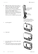
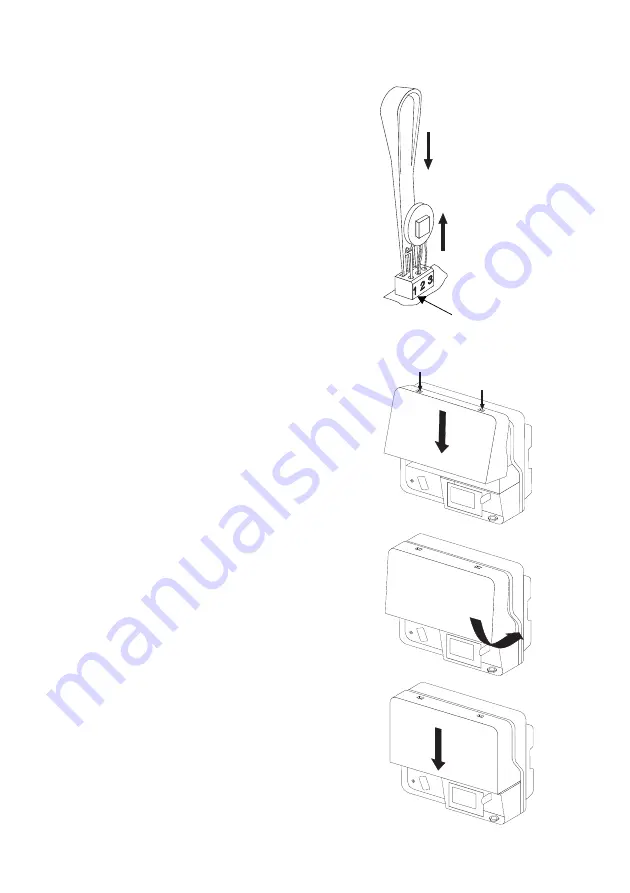
Replace all varistors with new ones as shown in 
this drawing. Varistor failure is generally due to 
influences which affect all varistors similarly 
(temperature, age, induced overvoltages).

If you do not receive a special tool for operating 
the terminal clamps together with your 
replacement varistors, please contact SMA. As an 
alternative, the terminal contacts can be operated 
using a 3.5 mm wide screwdriver. 

Ensure the varistor is installed the right way round!

9.

Insert the upper lid. 

10. Close the lid. 

11. Secure the two lid screws with the washers and a 

torque of 2.4 Nm.

12. Close the lower lid of the Sunny Boy as described 

in section 8.2 „Closing the Sunny Boy” (Page 51).

Insert the special 
tool to open the 
terminal

Remove 
the varistor

The pole with the small loop 
(crimp) must be fitted to terminal 1 
when replacing the varistor.

Содержание SUNNY BOY 4000TL

Страница 1: ...PV Inverter SUNNY BOY 4000TL 5000TL SB40TL_50TL IEN081211 IME TB SBXTL 20 Version 1 1 EN Installation Guide...

Страница 2: ...Bluetooth connection to other Sunny Boys Input voltage current Grid relay Event number grid Sunny Boy event number Power reduction due to excessive temperature Fan might need cleaning Sunny Boy might...

Страница 3: ...ivery 11 3 2 Check for Transport Damage 11 3 3 Identifying the Sunny Boy 11 4 Technical Data 12 5 Installation 17 5 1 Selecting an Installation Location 17 5 1 1 Dimensions and Weight 17 5 1 2 Ambient...

Страница 4: ...n Module 45 7 Commissioning 47 8 Opening and Closing 49 8 1 Opening the Sunny Boy 49 8 2 Closing the Sunny Boy 51 9 Maintenance 53 9 1 Checking Heat Dissipation 53 9 1 1 Cleaning the Fan 53 9 1 2 Test...

Страница 5: ...SMA Technologie AG Table of Contents Installation Guide SB40TL_50TL IEN081211 5 13 4 Disposal 71 14 Contact 72...

Страница 6: ...SMA Technologie AG 6 SB40TL_50TL IEN081211 Installation Guide...

Страница 7: ...e installation and commissioning of SMA Sunny Boy 4000TL SB 4000TL 20 and 5000TL SB 5000TL 20 type inverters 1 2 Target Group Only qualified electricians may install and commission Sunny Boy units 1 3...

Страница 8: ...oided will result in death or serious injury WARNING WARNING indicates a hazardous situation which if not avoided could result in death or serious injury CAUTION CAUTION indicates a hazardous situatio...

Страница 9: ...ing range of all components at all times The free design program Sunny Design www SMA de SunnyDesign will assist you in this The manufacturer of the PV modules must have approved the modules for use w...

Страница 10: ...ing body may become hot Only touch the lower housing lid during operation CAUTION Possible health risks due to the effects of radiation Do not spend long periods of time at a distance of less than 20...

Страница 11: ...er if you find any damage 3 3 Identifying the Sunny Boy You can identify the Sunny Boy using the name plate The name plate is on the right side of the housing Object Number Description A 1 Sunny Boy B...

Страница 12: ...ax 550 V a Input voltage MPP range UPV 125 V DC 440 V DC Max input current IPV max 2 x 15 A Max input power PDC 4300 W 5300 W Number of MPP trackers 2 Max no of strings parallel 2 x 2 Voltage ripple U...

Страница 13: ...ion of output current at THD 2 PAC 0 5 PACnom KIAC 4 Nominal AC voltage Operating range UACnom UAC 220 V 230 V 240 V 160 V 280 Vb AC grid frequency self adjusting Operating range fACnom fAC 50 Hz 60 H...

Страница 14: ...mperature range 25 C to 60 C extended humidity range 0 100 extended air pressure range 79 5 kPa to 106 kPa Transport of type E class 2K3 temperature range 25 C 70 C Operating temperature range 25 C 60...

Страница 15: ...max 97 0 CEC rebate efficiency euro 96 2 96 5 Communication interfaces Bluetooth as standard RS485 galvanically isolated optional Electronic Solar Switch ESS Electrical service life in case of a shor...

Страница 16: ...Technical Data SMA Technologie AG 16 SB40TL_50TL IEN081211 Installation Guide Efficiency curve...

Страница 17: ...Sunny Boy housing can become hot during operation Do not mount the Sunny Boy on flammable construction materials Do not mount the Sunny Boy in areas where highly flammable materials are stored Do not...

Страница 18: ...not install the unit on plasterboard walls etc as otherwise audible vibrations are likely to result The Sunny Boy can make noises which may be regarded as a nuisance if it is installed in a living ar...

Страница 19: ...ion Vertical installation or tilted back 15 max Never install the unit with a forward tilt Do not install horizontally Install at eye level to allow operating conditions to be read at all times 5 2 In...

Страница 20: ...meter 18 mm 3 Transport the Sunny Boy using the handles at the sides of the Sunny Boy 4 Attach the Sunny Boy to the wall bracket slightly to the left of its final position The right edge of the rear w...

Страница 21: ...uide SB40TL_50TL IEN081211 21 5 Check both sides to ensure that it is correctly in place 6 Push the Sunny Boy to the right on the wall bracket until it locks into place with the locking bolt on the re...

Страница 22: ...can be secured to the wall bracket with a lock to protect it against theft The lock must meet the following requirements Size A 6 10 mm in diameter B 21 35 mm C 20 33 mm D 40 60 mm E 13 21 mm Stainle...

Страница 23: ...erial suitable for the surface only Take into account the weight of the Sunny Boy when selecting fastening materials Mounting procedure 1 Use the top hat rail as a drilling template and mark the posit...

Страница 24: ...he Sunny Boy being pulled off you must also screw it to the wall To do so proceed as follows 1 Remove the Electronic Solar Switch by pulling it downwards 2 Loosen all six non removable lid screws and...

Страница 25: ...llation Guide SB40TL_50TL IEN081211 25 6 Secure the Sunny Boy with a screw The screw must meet the following requirements 7 Ensure that it is securely tightened Length min 100 mm Diameter 8 mm Screw h...

Страница 26: ...uit If cables with different voltages are laid parallel to one another short circuits can result if the cable insulation becomes damaged Lay all cables separately NOTICE Electrostatic discharges can d...

Страница 27: ...tional E Plug for connecting the fault signaling contact optional F Terminal for the mains supply connection G Cable opening for grid connection AC 12 25 mm H Cable opening for the fault signaling con...

Страница 28: ...grid impedance should not exceed 1 Ohm Otherwise the Sunny Boy will deactivate at full feed in power due to excessive voltage at the grid connection point The cable cross section should be sized usin...

Страница 29: ...t being reactivated 3 Remove the Electronic Solar Switch WARNING Risk of lethal burns When a generator Sunny Boy and a consumer are connected to the same line circuit breaker the protective function o...

Страница 30: ...Page 27 slightly and remove the dummy plug from the cable opening Other connections and settings If you want to make other connections than AC and DC you should make them now before connecting the AC...

Страница 31: ...There is a two part seal in the screw clamp If necessary the inner insert can be removed to insert a thicker cable The following guideline values apply Cable cross section with both seals 12 16 mm Ca...

Страница 32: ...ve earth on the connection terminal of the housing Proceed as follows 1 Loosen screw A halfway 2 Insert the stripped grounding cable D under the terminal clamp max cross section 16 mm 3 Screw the term...

Страница 33: ...ngs can be attached to each of the two input areas They must fulfill the following requirements Per input area A or B the following requirements of the connected modules apply Same type Same number Id...

Страница 34: ...ed Check the system design if the open circuit voltage of the solar modules is less than 10 below the maximum input voltage of the Sunny Boy No mixed connection of input areas For example if the plus...

Страница 35: ...e Sunny Boy could be irreparably damaged by overvoltage If the voltage of the solar modules exceeds the maximum input voltage of the Sunny Boy it could be irreparably damaged by overvoltage All warran...

Страница 36: ...an now commission the Sunny Boy as described in section 7 Commissioning Page 47 The following connections and settings are optional NOTICE Damage to the Electronic Solar Switch If inserted incorrectly...

Страница 37: ...countries require a device which prevents the parameters for grid feeding being changed For this reason some country data sets are protected Protected country data sets are automatically blocked 10 f...

Страница 38: ...parameter set are specified in the operation parameters You can view these using a communication device or download it from www SMA de 1 2 Parameter set Display language Protection Country 0 0 Conditi...

Страница 39: ...e them using a communication device or copy settings to the Sunny Boy using an SD card 3 0 DK5940E2 2 Italian no Italy 3 8 German no Italy 4 0 RD1663 Spanish yes Spain 4 8 PPC Greek no Greece 5 0 Kepc...

Страница 40: ...1 Opening the Sunny Boy Page 49 2 Set the arrows on the rotary switches to the required position using a screwdriver 2 5 mm 3 Close the Sunny Boy as described in section 8 2 Closing the Sunny Boy Pag...

Страница 41: ...cessary if the adjacent system is within 500 m of your system All inverters in your system must have the same Bluetooth ID to ensure that they are registered by your communication device To do so proc...

Страница 42: ...onsumer both in the event of errors and for trouble free operation The following voltages and currents can be connected Cable requirements The cable type and laying method must be suitable for the app...

Страница 43: ...1 Opening the Sunny Boy Page 49 3 Loosen the union nut of the screw clamp see H on Page 27 slightly and remove the dummy plug from the cable opening B F B F B F B F B F B F Trouble free operation B E...

Страница 44: ...clamp tightly to the cable opening again 9 Close the Sunny Boy as described in section 8 2 Closing the Sunny Boy Page 51 10 Switch on the supply voltage Seal in the screw clamp There is a two part se...

Страница 45: ...ceed as follows 1 Open the Sunny Boy as described in section 8 1 Opening the Sunny Boy Page 49 2 Open the screw of the display and flip the display up until it locks into place 3 4 Insert the communic...

Страница 46: ...081211 Installation Guide 6 Wire the communication module as described in the module documentation 7 Flip down the display and secure it 8 Attach the ribbon cable to the connector 9 Close the Sunny Bo...

Страница 47: ...in place The Electronic Solar Switch is securely plugged The AC distribution is installed correctly Commissioning procedure 1 Switch on the line circuit breaker 2 If the radiation is sufficient an ill...

Страница 48: ...me of the inverter can be changed using a communication device 3 After a further 5 seconds or when you knock again the standard configured is displayed 4 After a further 5 seconds or when you knock ag...

Страница 49: ...fore you touch a component DANGER Lethal danger caused by high voltages in the Sunny Boy Before you open the Sunny Boy Switch off the line circuit breaker and secure it to prevent it being reactivated...

Страница 50: ...rminal to ensure that there is no voltage present at PE The maximum diameter of the test tip may not exceed 2 mm If voltage is found check the installation 6 Ensure there is no voltage present at the...

Страница 51: ...screws Tighten the screws in the sequence shown on the right to a torque of 1 4 Nm 3 Check the Electronic Solar Switch for wear as described in section 9 2 and connect it after successful testing DANG...

Страница 52: ...flashes for an extended period this may be due to the fact that the DC radiation is not sufficient Measurements can only be made if the DC radiation is sufficient 7 The meaning of the illuminated red...

Страница 53: ...g fins and ventilation channels with a soft brush if necessary Clean the fan as described below 9 1 1 Cleaning the Fan If the fan is only covered in loose dust it can be cleaned with a vacuum cleaner...

Страница 54: ...e housing wall when inserted in the Sunny Boy 9 The fan can be tested for function using a communication component as described in the following section 9 1 2 Testing the Fan 1 Request the installer p...

Страница 55: ...on the inside of the plug for brown discoloration If at least one of the metal tongues is brown or fully burned off see figure above the Electronic Solar Switch can no longer be guaranteed to functio...

Страница 56: ...GB of storage space Firmware update 1 Save the required files on the SD card in the following directory SD card drive UPDATE 2 Open the Sunny Boy as described in section 8 1 Opening the Sunny Boy Page...

Страница 57: ...omplete is shown on the display and you can remove the SD card again 9 Open the Sunny Boy as described in section 8 1 Opening the Sunny Boy Page 49 10 Push the SD card in a little and release it The S...

Страница 58: ...valid for max 10 feed in hours No new update on SD card There is no update file relevant for this Sunny Boy on the SD card or the update present has already been implemented Grid parameters unchanged...

Страница 59: ...dy 1 Grid overvoltage The grid voltage exceeds the permitted range The fault can have the following causes The grid voltage at the connection point of the Sunny Boy is too high The grid impedance at t...

Страница 60: ...protection The average grid voltage over 10 minutes is no longer within the permissible range This can be due to either of the following reasons The grid voltage at the connection point of the Sunny...

Страница 61: ...scuss with the utility operator whether the monitoring threshold can be raised 7 Grid frequency not permitted The grid frequency is outside the permitted range For reasons of safety the Sunny Boy disc...

Страница 62: ...put voltage at the Sunny Boy is too high Disconnect the Sunny Boy from the PV generator immediately as described in section 8 1 Opening the Sunny Boy Page 49 Otherwise the Sunny Boy could be irreparab...

Страница 63: ...d Fault Monitoring Page 67 Have the PV generator installation engineer fix the ground fault before you can reconnect the string in question 38 DC overcurrent Overcurrent occurs on the DC side of the S...

Страница 64: ...ive Format SD card Save data on the SD card again Parameter file missing or faulty Copy the parameter file to the directory SD card drive PARASET Could not set parameters Check parameters for valid va...

Страница 65: ...fault but the Sunny Boy continues to feed power Display update failed Internal device fault but the Sunny Boy continues to feed power Language table update failed Internal device fault but the Sunny...

Страница 66: ...r a valid Inst code to change the country data set Waiting for main system The DC voltage at the DC input is not sufficient to operate the main computer The selected rotary switch setting is not assig...

Страница 67: ...ground potential If a voltage is present there is a ground fault in the corresponding string The approximate position of the ground fault can be determined from the ratio of the measured voltages betw...

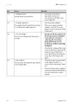
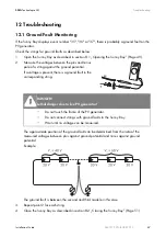
Страница 68: ...overvoltages It is therefore possible that one of the thermally monitored varistors has lost its protective function Check the varistors as described below 1 Open the Sunny Boy as described in section...

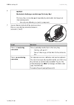
Страница 69: ...omponents Ground yourself before you touch a component Event Measure There is a conducting connection There is probably another fault in the Sunny Boy Continue with point 9 Discuss further steps with...

Страница 70: ...our replacement varistors please contact SMA As an alternative the terminal contacts can be operated using a 3 5 mm wide screwdriver Ensure the varistor is installed the right way round 9 Insert the u...

Страница 71: ...nny Boy in the original packaging If this is no longer available you can use an equivalent box which fulfills the following requirements Suitable for loads of at least 25 kg With handle system Can be...

Страница 72: ...ollowing information available when you contact SMA Inverter type Serial number of the Sunny Boy Type and number of modules connected Event number or display of the Sunny Boy Type of communication if...

Страница 73: ...SMA Technologie AG Contact Installation Guide SB40TL_50TL IEN081211 73...

Страница 74: ...Contact SMA Technologie AG 74 SB40TL_50TL IEN081211 Installation Guide...

Страница 75: ...nd instructions contained in all documents relevant to the product Operating the product under incorrect safety or protection conditions Altering the product or supplied software without authority The...

Страница 76: ...A Technologie AG Hannoversche Strasse 1 5 34266 Niestetal Germany Tel 49 561 9522 4000 Fax 49 561 9522 4040 Email sales SMA de Freecall 800 SUNNYBOY Freecall 800 78669269 Innovation in Systems Technol...

Отзывы: