background image

13  Technical Data

SMA Solar Technology AG

72

REDUCERBOX-BA-en-16

User Manual

13 Technical Data

13.1 Power Reducer Box

Mechanical Data

Ambient Conditions during Operation

Ambient Conditions for Storage/Transport

Communication

Mounting

Width x height x depth

255 mm x 130 mm x 57 mm

Weight

750 g

Degree of protection

IP20

Ambient temperature

− 20°C … +60°C

Relative humidity*

* non-condensing

5% … 95%

Maximum operating altitude above 
Mean Sea Level

2,000 m

Degree of protection**

** according to DIN EN 60529

IP20

Ambient temperature

− 40°C … +70°C

Relative humidity*

* non-condensing

5% … 95%

Maximum operating altitude above 
Mean Sea Level

3,000 m

Sunny WebBox/Sunny WebBox with 

Bluetooth

®

 Wireless Technology

Ethernet

Computer

Ethernet

Maximum range

100 m

Maximum number of Sunny WebBoxes

50

Mounting location

Indoors

Type of mounting

Top-hat rail mounting, wall mounting

Содержание POWER REDUCER BOX

Страница 1: ...REDUCERBOX BA en 16 98 0018716 Version 1 6 EN Device for Power Control of PV Plants POWER REDUCER BOX User Manual...

Страница 2: ......

Страница 3: ...Precautions 11 2 5 Operating Instructions 12 3 Scope of Delivery 13 4 Product Description 14 4 1 Power Reducer Box 14 4 2 Type Label 17 4 3 LEDs 18 4 4 Sunny Portal 18 4 5 System Requirements of the C...

Страница 4: ...8 1 3 Setting the Computer to the Standard Network Settings of the Power Reducer Box 32 8 1 4 Setting up a Proxy Exception Rule in Internet Explorer 34 8 1 5 Setting the Power Reducer Box to Local Ne...

Страница 5: ...10 1 3 Deactivating Data Transmission to the Sunny Portal 52 10 2 Changing your Password 53 10 3 Resetting your Password 53 10 4 Setting the Date and Time 54 10 5 Setting Protocol Files 54 10 6 Firmwa...

Страница 6: ...f the LEDs at the Ethernet Terminal 62 12 3 General Troubleshooting 63 12 4 Error Messages in Connection with Sunny Portal 65 12 4 1 Error Messages in the Events Logbook 65 12 4 2 Errors During Regist...

Страница 7: ...onal Information Links to additional information can be found at www SMA Solar com Symbols Document title Document type Reactive Power and Grid Integration Technical information Symbol Explanation Ind...

Страница 8: ...cted Select Settings Date Button Key Button or key to be selected or pressed Select Next Full designation Designation in this document Electronic Solar Switch ESS SMA Bluetooth Wireless Technology Blu...

Страница 9: ...r Box primarily performs the following tasks Active power limitation and reactive power setpoint Recording all control commands of the network operator Control of up to 2 500 SMA inverters via Sunny W...

Страница 10: ...h Bluetooth firmware version 1 04 or later Sunny Portal SMA Update Portal Requirements the transmission protocol of your plant must be set to SMA NET and the Sunny WebBoxes must not be operated in DHC...

Страница 11: ...may normally only be changed after consultation with the power supply company into whose electricity grid you are feeding If you have any doubts contact your power supply company Electrostatic Dischar...

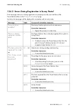
Страница 12: ...e unsupported inverters must be disconnected via a suitable switching unit If in doubt contact your network operator or the SMA Service Line before you commission the Power Reducer Box No DCHP Mode in...

Страница 13: ...ecialist dealer if the delivery is incomplete or damaged Figure 1 Components included in scope of delivery Item Quantity Description A 1 Power Reducer Box B 1 Plug in power supply with 4 adapters C 1...

Страница 14: ...optimal notification to the plant operator Four digital states e g a ripple control receiver can be imported with the Power Reducer Box and the inverters can be set according to the specifications of...

Страница 15: ...ser Manual REDUCERBOX BA en 16 15 Figure 2 Principle of implementing grid management with the Power Reducer Box and the Sunny WebBox Figure 3 Principle of implementing grid management with the Power R...

Страница 16: ...power output Connecting the Power Reducer Box to the local network The diagram for the principle of implementing grid management does not replace the exact terminal assignment for connecting the Power...

Страница 17: ...type label must be permanently attached to the Power Reducer Box Symbols on the Type Label Item Explanation A Device type B Serial number C Device specific characteristics Symbol Description Explanati...

Страница 18: ...Portal plant logbook In addition the Sunny Portal can inform the user of actual events via e mail see Sunny Portal for Sunny WebBox user manual LED Meaning POWER COMMAND Validity of the setpoint POWE...

Страница 19: ...tem Requirements of the Computer Supported Internet browsers Microsoft Internet Explorer from version 8 Mozilla Firefox from version 3 6 Google Chrome from version 23 0 Apple Safari from version 5 1 7...

Страница 20: ...revent two users effecting contradictory settings at the same time only one user can ever be logged on to the Power Reducer Box at one time In addition to the rights of the User user group the Install...

Страница 21: ...User Manual REDUCERBOX BA en 16 21 5 2 Overview of the Login Page Figure 6 Login page of the Power Reducer Box on the computer Item Description A Device status B Language selection C Login area D Ser...

Страница 22: ...erface Figure 7 Layout of the user interface 5 4 Main menu Item Description A Main menu B Context menu C Content area Button Function This button opens the Status page see Section 5 6 Status Page page...

Страница 23: ...ion 4 4 Sunny Portal page 18 Update settings This menu item opens the Update settings page see Section 10 6 Firmware Update for the Power Reducer Box page 55 Device status The device status displays t...

Страница 24: ...al memory Once the internal memory has reached its capacity the oldest events will be overwritten In addition you can download events in CSV format as well as save events to an SD card Symbol Status D...

Страница 25: ...digital connection between the Power Reducer Box and the ripple control receiver must not exceed 30 m The device should be located near to a 230 V socket outlet The cable feeds require approximately...

Страница 26: ...holes with a diameter of 6 mm at the marked points 4 Insert wall plugs into the holes 5 Screw in the screws and leave approximately 6 mm protruding from the wall 6 Hang the Power Reducer Box on the s...

Страница 27: ...Overview of the Connection Area Figure 9 Overview of the connection area All other connections on the Power Reducer Box have no function Item Description A Connection for the plug in power supply B A...

Страница 28: ...educer Box cable to line conductors of the ripple control receiver The exact wiring is shown in the following circuit diagram When connecting ensure that no phase bridge has been used in the ripple co...

Страница 29: ...am 2 Plug the 7 pole plug into the AUXCOM terminal on the Power Reducer Box The Power Reducer Box is connected to the ripple control receiver Insulated wire colour DIN 47100 without colour repetition...

Страница 30: ...lied cable 2 Remove 4 cm of the cable sheath from the cable to be connected 3 Strip approximately 6 mm of insulation off the wires 4 Twist the cable shield and plug it into a heat shrink tubing 5 Fit...

Страница 31: ...e 1 Connecting the Power Reducer Box to the Computer Section 8 1 2 2 Setting the computer to the Standard Network Settings of the Power Reducer Box Section 8 1 3 3 When using a proxy server Setting up...

Страница 32: ...Pv4 Properties window opens 7 Make a note of the existing network settings in the Internet Protocol Version 4 TCP IPv4 Properties window With this you can reset the computer to the previous network se...

Страница 33: ...erties The Local Area Connection Properties window opens 5 Select Internet Protocol TCP IP and click Properties The Internet Protocol TCP IP Properties window opens 6 Make a note of the existing netwo...

Страница 34: ...Reducer Box in the Internet Explorer address bar http 192 168 0 200 The Power Reducer Box home page appears 8 1 5 Setting the Power Reducer Box to Local Network Settings You can allocate static networ...

Страница 35: ...s the Ethernet network to certain IP addresses and separates the network areas from one another In the Gateway address field enter the gateway address of your network The gateway address is the IP add...

Страница 36: ...to the Local Network Using DHCP Before you set the Power Reducer Box to DHCP check whether your DHCP server can extend the lease time of the IP address allocated If the DHCP server allocates a new IP...

Страница 37: ...r supply from the socket outlet 2 Remove the blue Ethernet cable 3 Connect the Power Reducer Box and switch or router together using the Ethernet terminals Use the red Ethernet cable to do this 4 Conn...

Страница 38: ...bBox is entered as default 1 In the IP address field enter the IP address at which the Sunny WebBox can be reached The Sunny WebBox must have a fixed IP address and must not be in DHCP mode Tip if you...

Страница 39: ...the Sunny WebBox to be removed The Sunny WebBox is deleted from the list These settings may only be configured by skilled persons The settings in this section may only be configured by a skilled pers...

Страница 40: ...s assigned with an operating mode and the operating mode is configured The input status is activated The following operating modes can be configured via the user interface Simple operating modes Effec...

Страница 41: ...SMA Solar Technology AG 8 Commissioning User Manual REDUCERBOX BA en 16 41 Figure 11 Status configuration page...

Страница 42: ...g General System Statuses page 44 9 Select Save The active power limitation is set 8 3 2 Setting the Reactive Power Setpoint 1 Log in as Installer 2 Select Status configuration in the context menu 3 S...

Страница 43: ...1 L2 and L3 The cos phi value can be between 0 10 and 1 00 Different line conductors are only interpreted by inverters with multiple line conductors see inverter manual In the case of single phase inv...

Страница 44: ...Box switches to the status Time interval in case of constant setting Example if 60 seconds is entered the Power Reducer Box would transmit a control command to the registered Sunny WebBoxes every 60...

Страница 45: ...ticed over a long period of time this can lead to yield losses If the fallback is activated and configured the Power Reducer Box retains the operating mode of the last valid input status in the event...

Страница 46: ...es page 40 7 Select Save Configure and activate fallback in consultation with the network operator Only configure and activate the fallback in consultation with the responsible network operator Upper...

Страница 47: ...2 Select the desired language in the Language field 3 Select the user group in the User group field 4 Enter the password in the Password field 5 Select Login The Power Reducer Box home page appears Lo...

Страница 48: ...age The Power Reducer Box login page appears 9 3 Filtering and Displaying Events 1 Select Events in the main menu The events of the current day are displayed 2 If necessary filter the events For this...

Страница 49: ...re not overwritten on the SD card If the SD CARD LED on the Power Reducer Box is red the SD card is full or write protected All events are saved onto the SD card daily to the directory Year Month PREF...

Страница 50: ...SD card into the SD card slot on the Power Reducer Box The events are saved in the internal memory and additionally to the SD card You can carry out further settings on the protocol file in the system...

Страница 51: ...ings 5 Using the Communication monitoring drop down list set how often the Power Reducer Box should report to the Sunny Portal If the Power Reducer Box does not report to the Sunny Portal within the s...

Страница 52: ...ox is registered in Sunny Portal 10 1 2 Removing a Power Reducer Box Registered in Sunny Portal from a Plant In the following cases a Power Reducer Box registered in Sunny Portal must be removed from...

Страница 53: ...e active at the next login 10 3 Resetting your Password 1 Select Password settings in the context menu 2 In the Reset password area select the user group that is to be reset 3 Select Reset The passwor...

Страница 54: ...es 1 Select Network and system settings in the main menu 2 In the Prefix for protocol files field select the prefix with which the file name of the protocol file should begin 3 In the Language in prot...

Страница 55: ...Download update at hh mm 24 hour format field enter the time at which the Power Reducer Box should download the update 4 Select Save 10 6 2 Performing a Manual Firmware Update 1 Select Update settings...

Страница 56: ...s running During the update the Power Reducer Box restarts During the restart the Power Reducer Box does not implement settings The configured settings remain the same After the update has successfull...

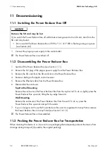
Страница 57: ...rements You must be a trained electrically skilled person The Power Reducer Box must be supplied with voltage Using a sharp object push the rest button in the hole The Power Reducer Box is reset 10 8...

Страница 58: ...rail To do so lightly press the Power Reducer Box upwards tilting the top edge forwards Wall Mounting Remove the enclosure of the Power Reducer Box from the wall To do so press the Power Reducer Box...

Страница 59: ...Manual REDUCERBOX BA en 16 59 11 4 Disposing of the Power Reducer Box Dispose of the Power Reducer Box at the end of its service life in accordance with the disposal regulations for electronic waste t...

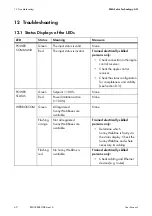
Страница 60: ...eck the status configuration for completeness and validity see Section 8 3 POWER STATUS Green Setpoint 100 None Red Power limitation active 100 None WEBBOXCOM Green All registered Sunny WebBoxes are a...

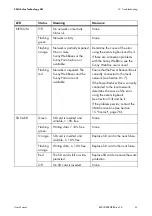
Страница 61: ...that the Power Reducer Box is correctly connected to the local network see Section 8 1 7 If the Power Reducer Box is correctly connected to the local network determine the cause of the error using th...

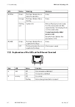
Страница 62: ...the socket outlet and after approximately 1 minute plug it back in to the socket outlet Trained electrically skilled persons only Reset the Power Reducer Box see Section 10 7 POWER Green The Power Re...

Страница 63: ...see Section 8 1 3 The network settings of the router do not correspond to the Power Reducer Box network settings Corrective measures Set the router to the Power Reducer Box network settings If necess...

Страница 64: ...damaged network components patch cables or plug connectors Check whether the network settings of the individual network components are correct Adapt the network settings if required Restart the Power...

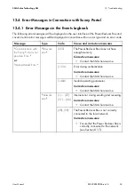
Страница 65: ...unny Portal is not possible Error or Upload failed Error Firmware error 255 The Power Reducer Box does not have enough memory Corrective measures Contact the SMA Service Line 1313 Error during authent...

Страница 66: ...rver are not correct Corrective measures Check the settings for the proxy server on the Sunny Portal settings page 400 Incorrect request of the Power Reducer Box Corrective measures Contact the SMA Se...

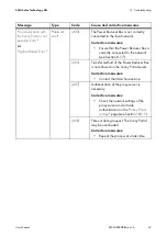
Страница 67: ...e network see Section 8 1 7 405 Transfer method of the Power Reducer Box is not allowed on the Sunny Portal server Corrective measures Contact the SMA Service Line 407 Authentication of the proxy serv...

Страница 68: ...verloaded or is currently down for maintenance Corrective measures Repeat the process at a later time 504 Gateway timeout The Sunny Portal may be overloaded or is currently down for maintenance Correc...

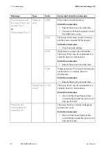
Страница 69: ...ered for a plant in Sunny Portal Corrective measures If desired remove the Power Reducer Box from the plant in Sunny Portal see Section 10 1 2 and reregister it see Section 10 1 1 The device cannot be...

Страница 70: ...ct the SMA Service Line 407 Authentication of the proxy server is necessary Corrective measures Check the network settings of the proxy server and activate authentication on the Sunny Portal settings...

Страница 71: ...sion Corrective measures Contact the SMA Service Line 1312 Error in Sunny Portal Corrective measures Repeat the process at a later time If the error continues to persist contact the SMA Service Line 1...

Страница 72: ...mbient temperature 20 C 60 C Relative humidity non condensing 5 95 Maximum operating altitude above Mean Sea Level 2 000 m Degree of protection according to DIN EN 60529 IP20 Ambient temperature 40 C...

Страница 73: ...power consumption 4 W Ripple control receiver 4 digital inputs Ethernet RJ45 Data rate 10 Mbit or 100 Mbit per second Prefabricated cable length 2 5 m Maximum permissible cable length 30 m Cable type...

Страница 74: ...ogy AG 74 REDUCERBOX BA en 16 User Manual 13 2 Plug in Power Supply CINCON TRG30R 120 Mechanical Data Voltage Supply Width x height x depth 107 8 mm x 57 5 mm x 33 5 mm Weight 300 g Voltage 100 V 240...

Страница 75: ...SMA Solar Technology AG 14 Accessories User Manual REDUCERBOX BA en 16 75 14 Accessories Description Brief description SMA order number SD card Memory card with a memory capacity of 2 GB SD CARD2GB...

Страница 76: ...the necessary assistance Information on the Ethernet network used Information on the PV plant The prb cfg configuration file and the log file from the SD card Firmware versions of the Power Reducer Bo...

Страница 77: ......

Страница 78: ......

Страница 79: ...r device These are also available online at www SMA Solar com and can be downloaded and are available on paper from the usual sales channels if required Trademarks All trademarks are recognised even i...

Страница 80: ...USBMJB 1UZ UE XXX 4 VTUSBMJB DPN BV 4 FOFMVY 413 XXX 4 FOFMVY DPN 4 FJKJOH PNNFSDJBM P UE XXX 4 IJOB DPN 4 FDI 3FQVCMJD T S P XXX 4 FDI DPN 4 SBODF 4 4 XXX 4 SBODF DPN 4 FMMBT XXX 4 FMMBT DPN 4 C SJDB...

Отзывы: