Sunny Boy 2500U
Installation and Operator’s Manual
SB2500U-11:NE
-
21
-
SMA Regelsysteme GmbH
First switching on
Please follow the order described when commissioning the device.
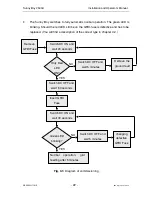
Fig. 3.1: Diagram of commissioning” provides a sequence chart for commissioning.
NOTE
: Following this procedure you will make sure that the PV-panel is iso-
lated from earth and the GFDI-fuse is not defective without using any addi-
tional measuring instrument.
•
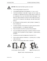
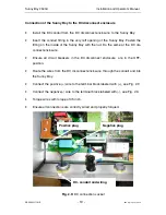
Remove the GFDI-fuse from the Sunny Boy (see Fig. 2.5).
•
Connect the grid voltage by switching ON the main 240 V AC-circuit breaker of
the supply lead.
•
Uncover the PV-panel. At sufficient insolation the PV-panel produces the re-
quired output power for supplying the Sunny Boy.
•
Switch ON the DC-circuit breaker in the DC disconnect enclosure . Now the
Sunny Boy is supplied with the DC-voltage and starts to operate.
•
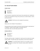
If the PV-panel is isolated from earth first the yellow and red LEDs and after
approx. 20 seconds only the red LED is on at the Sunny Boy. If you have
communication equipment you will be displayed the “GFDI-Fuse open” failure.
Should
both
the red
and
the yellow LEDs still be on there is a ground fault of the
PV-panel. If you have communication equipment you will be displayed the
“EarthCurrentMax” failure. The ground fault has to be removed. Then the com-
missioning procedure described above has to be repeated until only the red
LED is on.
•
When you have made sure the PV-panel is isolated from earth (only red LED
on) switch the DC-breaker OFF.
•
Wait until the LEDs at the device have turned off (max. 5 minutes).
•
Screw the GFDI-fuse into the fuse holder at the Sunny Boy again.
•
Switch the DC-breaker ON again so that the Sunny Boy is supplied with the DC-
voltage.

