4 Product Overview
SMA Solar Technology AG
Installation Manual
EDMM-WAGO-IO-IA-en-11
16
4.8
LED Signals
LED signals of the fieldbus coupler
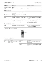
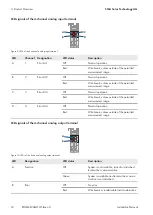
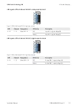
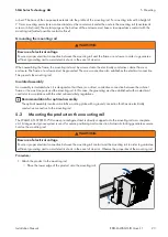
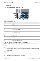
The LEDs indicate the operating state of the fieldbus coupler or the entire fieldbus node. The LEDs are assigned to
various diagnostic areas in groups.
A
B
C
D
E
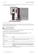
Figure 7: Fieldbus coupler LEDs
Position
LED group
Diagnostic area
A
LINK ACT Port 1
Fieldbus status
B
LINK ACT Port 2
C
MS (module status)
D
NS (network status)
E
OK
Node status
Evaluating the fieldbus status
The operating state of the communication via fieldbus is indicated via the upper LED group:
LINK ACT 1
,
LINK ACT
2
,
MS
, and
NS
.
The two-color LEDs
MS
(module status) and
NS
(network status) are only used by the Ethernet/IP protocol. The
indications of these two LEDs comply with the Ethernet/IP specification.
LED status
Description
Corrective measures
LINK ACT 1
,
LINK ACT 2
Green
The fieldbus node is connected to the physi-
cal network.
-
Flashing green
The fieldbus node is sending or receiving Eth-
ernet telegrams.
-
Off
The fieldbus is not connected to the physical
network.
1. Check the fieldbus cable.
MS
(module status)
Green
The system is working properly.
-
Flashing green
The system is not yet configured.
-
Red
The system indicates an error that cannot be
corrected.
1. Switch the supply voltage off and on
again to restart the system.
2. If the error is not resolved, please
contact WAGO I/O support.
Содержание Modbus EDMM-10
Страница 54: ...www SMA Solar com...


