4 Product Overview
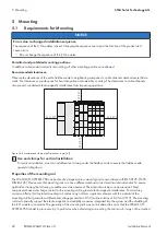
SMA Solar Technology AG
Installation Manual
13
EDMM-WAGO-IO-IA-en-11
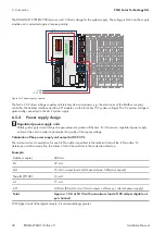
For the diagnostics of the different areas for the fieldbus coupler and fieldbus nodes, the LEDs can be divided into
corresponding groups.
A
B
C
D
E
Figure 4: Fieldbus coupler LEDs
Position
LED group
Color
Explanation
Fieldbus status
A
LINK ACT 1
green
Indicates a connection to the physical net-
work at Port 1.
B
LINK ACT 2
green
Indicates a connection to the physical net-
work at Port 2.
C
MS
Red/green
Indicates the node status.
D
NS
Red/green
Indicates the network status.
Node status
E
OK
Red/green/orange
Displays the local bus operation and indi-
cates errors with a blink code.
For detailed information on evaluation of the LED statuses(see Section 4.8 "LED Signals", page 16).
4.3
DC 24 V supply module
The supply module provides the bus terminals with the corresponding supply potential.
• Max. current via supply module: 10 A
• Max. voltage via power contacts: DC 24 V
• Max. current via power contacts: DC 10 A
Содержание Modbus EDMM-10
Страница 54: ...www SMA Solar com...


