MFR-NR-IA-en-23 | Version 2.3
ENGLISH
Installation Manual
MULTIFUNCTION RELAY
Страница 1: ...MFR NR IA en 23 Version 2 3 ENGLISH Installation Manual MULTIFUNCTION RELAY...
Страница 2: ...f not explicitly identified as such Missing designations do not mean that a product or brand is not a registered trademark The BLUETOOTH word mark and logos are registered trademarks owned by Bluetoot...
Страница 3: ...ctrical Connection Procedure 10 4 3 Overview of the Connection Area 11 4 4 Installing the Multifunction Relay 12 4 4 1 Mounting Position and Cable Route 12 4 4 2 Installing the Multifunction Relay in...
Страница 4: ...Table of Contents SMA Solar Technology AG 4 MFR NR IA en 23 Installation Manual...
Страница 5: ...ations Knowledge of the applicable standards and directives Knowledge of and compliance with this document and all safety information 1 3 Symbols Symbol Explanation Indicates a hazardous situation whi...
Страница 6: ...eter Elements to be selected Elements to be entered Select the parameter Operating mode of multifunction relay or Mlt OpMode and set the desired operating mode Complete designation Designation in this...
Страница 7: ...00TLHE 10 STP 15000TLEE 10 STP 20000TLEE 10 STP 15000TL 30 STP 20000TL 30 STP 25000TL 30 STP 10000TLEE JP 10 STP 20000TLEE JP 11 STP 25000TL JP 30 Use this product only in accordance with the informat...
Страница 8: ...lead to lethal electric shocks All work on the inverter must be carried out by qualified persons only Prior to performing any work on the inverter always disconnect the inverter from all voltage sour...
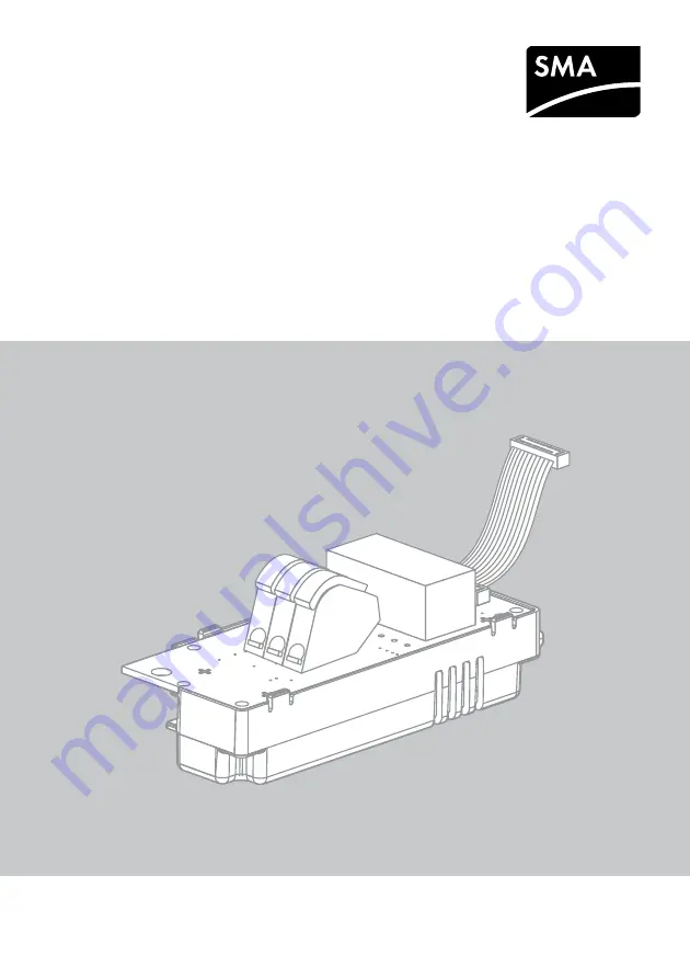
Страница 9: ...ible damage Contact your distributor if the scope of delivery is incomplete or damaged Figure 1 Components included in the scope of delivery Position Quantity Designation A 1 Multifunction relay This...
Страница 10: ...the inverter due to electrostatic discharge Touching electronic components can cause damage to or destroy the inverter through electrostatic discharge Ground yourself before touching any component Pro...
Страница 11: ...4 3 Overview of the Connection Area Figure 2 Design of the multifunction relay Position Designation A Connecting terminal plate for the connection to the multifunction relay B Ribbon cable for the co...
Страница 12: ...nting Position and Cable Route in the Sunny Tripower Figure 3 Installation area and cable route in the Sunny Tripower with the lower enclosure lid open and the display assembly flipped up Position Des...
Страница 13: ...e Sunny Boy Smart Energy Figure 4 Installation area and cable route in the Sunny Boy Smart Energy with the enclosure lid open and the display flipped up Position Designation A Inverter display B Insta...
Страница 14: ...oy Windy Boy Figure 5 Installation area and cable route in the Sunny Boy Windy Boy with the lower enclosure lid open and the display assembly flipped up Position Designation A Inverter display assembl...
Страница 15: ...of the display ribbon cable from the pin connector on the display assembly Flip the display down Press the right hand retainer outwards Pull the display out of the right hand retainer Pull the displa...
Страница 16: ...he inverter Lead the left hand key on the multifunction relay into the hole in the plastic retainer for the display assembly 5 Fasten the multifunction relay using the washer and the cylindrical screw...
Страница 17: ...relay into the hole in the plastic retainer for the display assembly 5 Lead the ribbon cable upwards behind the display assembly Displayed graphics This section describes the installation of the multi...
Страница 18: ...torque 1 5 Nm Use an Allen key AF 3 7 Flip the display assembly down 8 Tighten the screw of the display assembly 9 Insert the plug from the multifunction relay ribbon cable into the left hand pin conn...
Страница 19: ...isturbed operation of the inverter This operating mode is set by default Self consumption SelfCsmp The multifunction relay switches the loads on or off depending on the amount of power available from...
Страница 20: ...he multifunction relay as fault indicator contact Self consumption SelfCsmp Controlling loads or charging batteries in a power dependent way via the multifunction relay Control via communication ComCt...
Страница 21: ...rors This requires a parallel connection Alternatively you can choose to have the undisturbed operation displayed or reported This requires a series connection You can connect several inverters to one...
Страница 22: ...endent way via the multifunction relay To enable this function a contactor K1 must be connected to the multifunction relay The contactor K1 switches the operating current for the load on or off If you...
Страница 23: ...s of the Grid Relay The multifunction relay can trip a signal to the grid operator as soon as the inverter connects to the utility grid To enable this function the multifunction relays of all inverter...
Страница 24: ...insert the cable gland from the outside Unscrew the counter nut from the outside of the inverter and remove the cable gland from inside of the inverter Destruction of the multifunction relay as a resu...
Страница 25: ...nsert from the cable gland 6 Route the cable into the inverter through the cable gland 7 Dismantle the cable by no more than 15 mm 8 Strip off the conductor insulation by max 8 mm 9 Depending on the i...
Страница 26: ...set the desired value This determines the power threshold at which a load is switched on Select the parameter Minimum power On time MFR self consumption Mlt MinOnPwrTmm and set the desired value This...
Страница 27: ...voltage 240 V Maximum DC switching voltage 30 V Maximum AC switching current 1 0 A Maximum DC switching current 1 0 A Minimum electrical endurance when the maximum switching voltage and maximum switc...
Страница 28: ...eiz SMA Solar Technology AG Niestetal SMA Online Service Center www SMA Service com Sunny Boy Sunny Mini Central Sunny Tripower 49 561 9522 1499 Monitoring Systems Kommunikationsprodukte 49 561 9522 2...
Страница 29: ...Solar Thailand Co Ltd 66 2 670 6999 South Africa SMA Solar Technology South Africa Pty Ltd Cape Town 08600SUNNY 08600 78669 International 27 0 21 826 0600 Argentina Brasil Chile Per SMA South America...
Страница 30: ...ch 29 2014 EMC Low Voltage Directive 2014 35 EU L 96 357 374 March 29 2014 LVD Radio and telecommunications terminal equipment R TTE 1999 05 EC SMA Solar Technology AG confirms herewith that the assem...
Страница 31: ......
Страница 32: ...www SMA Solar com SMA Solar Technology...