6 Electrical Connection
SMA Solar Technology AG
Operating manual
MC-BOX-6-3-BE-en-30
17
Position
Designation
F
Terminals
Loads
for connecting the loads (N, grounding conductor (PE))
G
Terminals
PV-System
for connecting the PV system (L1, L2, L3, N, grounding con-
ductor (PE))
H
Miniature circuit breaker for connecting the Sunny Island (L)
I
Terminals
Clusters
for connecting the Sunny Island (N, grounding conductor (PE))
J
Terminal
X5 Equipotential Busbar
for connecting the grounding conductor (for
grounding the entire multicluster system)
6.1.2
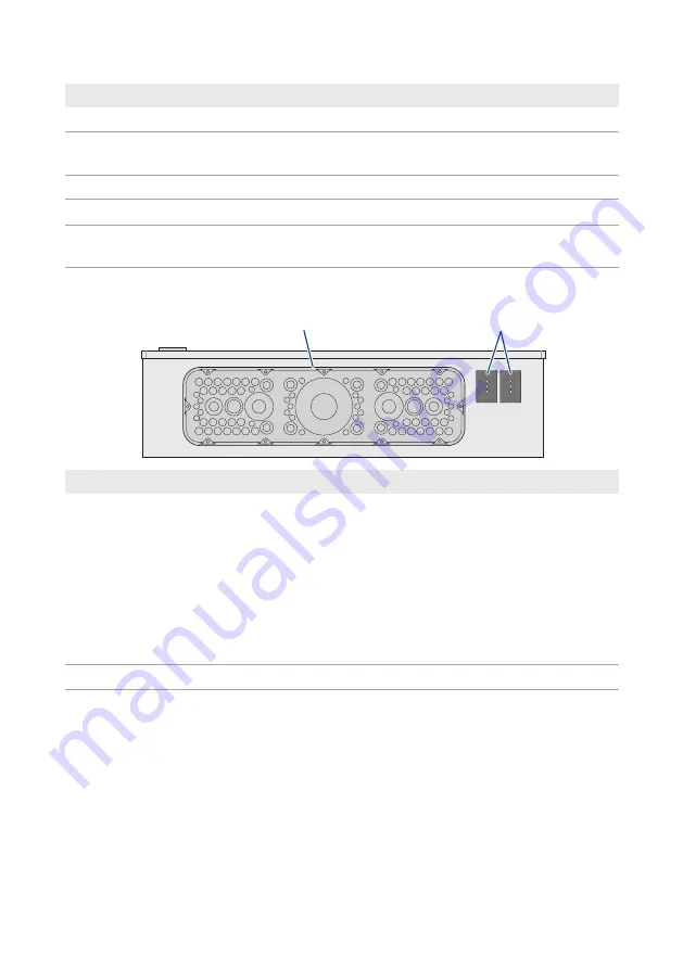
View from Below
A
B
Position
Designation
A
Base plate with membranes for inserting the power cables:
• 28 membranes for external cable diameters of 5 mm to 11 mm
• 48 membranes for external cable diameters of 10 mm to 15 mm
• 8 membranes for external cable diameters of 15 mm to 25 mm
• 2 membranes for external cable diameters of 19 mm to 34 mm
• 2 membranes for external cable diameters of 26 mm to 35 mm
• 2 membranes for external cable diameters of 26 mm to 54 mm
• 1 membrane for external cable diameters of 50 mm to 110 mm
B
Two-part cable feed-through for inserting the data cables
6.2
Connecting the Generator
You can connect a three-phase generator to the Multicluster-Box, e.g., a diesel generator or
another grid-forming power generator. However, you also have the option of connecting it to the
utility grid. The line conductors L1, L2, and L3 are routed via a fuse switch-disconnector in the
Multicluster-Box. Fuse links with a nominal current of 80 A are factory-installed.
Содержание MC-BOX-6.3-11
Страница 1: ...MC BOX 6 3 BE en 30 Version 3 0 ENGLISH Operating manual MULTICLUSTER BOX 6...
Страница 40: ...www SMA Solar com...


