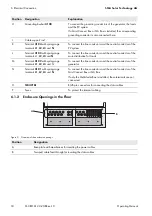
SMA Solar Technology AG
6 Electrical Connection
Operating Manual
MC-BOX-12-3-20-BE-en-10
19
6.2 Installing the Multicluster Box without Grid Connect Box or NA Box
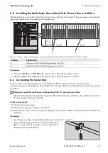
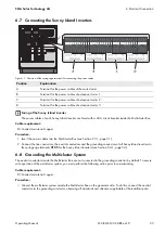
If the Multicluster Box is installed without Grid Connect Box or NA Box, the terminals of the grounding contactor and the
generator contactor must be equipped with a jumper wire.
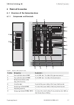
Figure 10: Overview of the provided jumper wires when installing the Multicluster Box without Grid Connect Box or NA Box
Procedure:
1. Short-circuit
X110:1
and
X110:2
with a jumper wire to block the grounding contactor.
2. Short-circuit
X111:6
and
X111:7
with a jumper wire to block the generator contactor.
6.3 Connecting the Generator
You can connect a three-phase generator to the Multicluster Box. The line conductors are routed via fuse
switch-disconnectors in the Multicluster Box. LV/HRC size 1 fuse links 200 A are installed in the fuse switch-disconnector
by default.
Cable requirements:
Conductor material: copper
Conductor cross-section: 120 mm² to 150 mm²
If the generator does not have an output fuse, the generator connection cables must be ground-fault and short-circuit
protected.
Procedure:
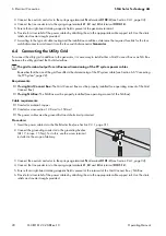
1. Insert the power cables into the Multicluster Box (see Section 9.3.1, page 31).
2. Connect the grounding conductor to the grounding busbar
(AF 17, torque: 15 Nm). To do this, use the screw terminal
included in the scope of delivery.
Position
Explanation
A
Jumper wire for blocking the grounding contactor
B
Jumper wire for blocking the generator contactor
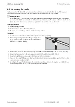
Generator output fuse influences dimensioning of the PV system power cables
Remember that the size of the generator output fuse affects the dimensioning of the PV system cable (see Section 6.6

