SMA America, LLC
7 Commissioning
Installation Manual
SB3-5TLUS22-IA-en-12
51
7.2 Commissioning the Inverter
Requirements:
☐ AC overcurrent protection and AC disconnecting unit must be correctly designed.
☐ The inverter must be correctly mounted and closed.
☐ The DC Disconnect must be correctly mounted and closed.
☐ All cables must be correctly connected.
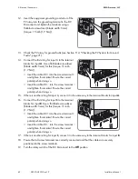
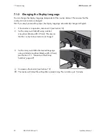
1. Place the lower enclosure lid with the 6 screws onto
the enclosure and tighten them using an Allen key
(AF 3) in the order 1 to 6 (torque: 18 in-lbs. (2.0 Nm).
2. Switch on or close all AC disconnecting switches and circuit breakers in the output circuit of the
inverter.
3. If an external DC disconnecting switch is available, switch on or close the DC disconnecting
switch.
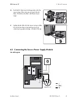
4. Turn the rotary switch of the DC Disconnect to the
On
position.
☑ The inverter carries out an arc-fault circuit interrupter (AFCI) self test.
☑ The green LED is lit and the display shows the device type, the firmware version, the device
names, the country data set and display language. If communication is via Zigbee
®
or
Speedwire, then the Zigbee
®
status and the versions of the communication assemblies will also
be displayed also after the device names.
The inverter feeds into the grid.
✖ Green LED flashing?
Possible cause of error: The DC input voltage is still too low, or the inverter is monitoring the
utility grid.
• Once the DC input voltage is sufficiently high, the inverter goes into operation.
✖ The red LED is lit and an error message and event number appear in the display?
• Eliminate the error (see Section 11 "Troubleshooting", page 59).
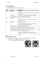
✖ The blue LED is glowing or flashing?
• Eliminate the communication error (see Section 9.3 "LED Signals", page 54).
Содержание 3000TL-US
Страница 2: ......
Страница 86: ......
Страница 87: ......
Страница 88: ...www SMA Solar com SMA Solar Technology SMA America LLC www SMA America com ...

