Sleipner SE20/110 Скачать руководство пользователя страница 11

 11

5611

12

2021

-

SE20 & SE25 & SE30 & SE40


MG_0005

R

D

1

2

3

4

6

5

8 x layers of fiberglass 

and resin

8 x layers of fiberglass 

and resin

MG_0006

R = D x 0,1

R = D x 0,1

D x

 0,1

-0,1

5

D x

 0,1

-0,

15

D

Layers of 

fiberglass 

and resin

Layers of 

fiberglass 

and resin

*Fiberglass 

Hull

*Steel/ 

Aluminium 

Hull

Hull

Hull

Hull

Tunnel

Tunnel

Tunnel

Welding

Layers of 

fiberglass 

and resin

Additional Layers of 

fiberglass and resin

Additional Layers of 

fiberglass and resin

Hull

1

3

4

2

Tunnel Installation

EN

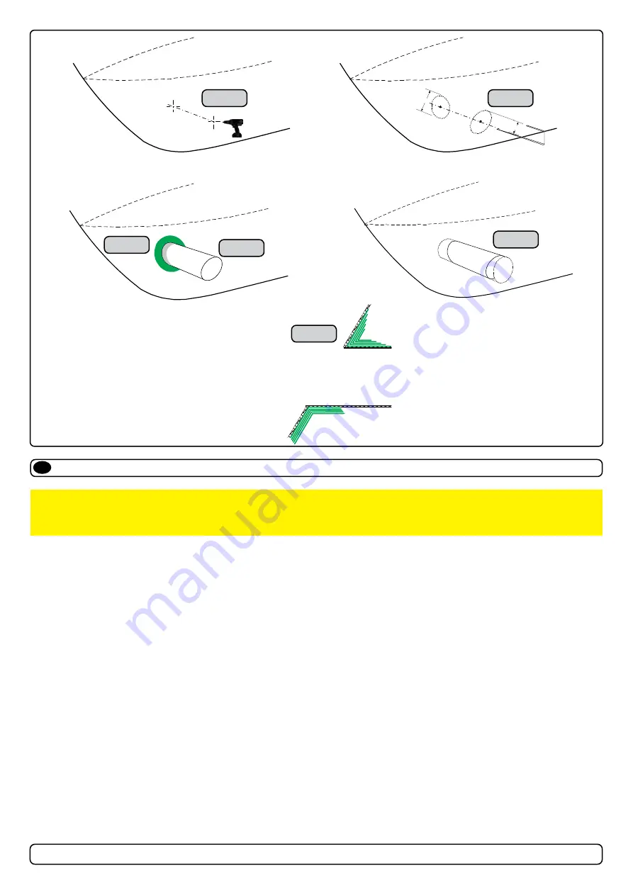
1.  Find the position in the boat considering the information earlier in this manual and the applicable measurements for the thruster model you are 

installing. Mark the centre of the tunnel on both sides of the hull. Drill a hole horizontally at these marks. 

2.   Mark the circle for the tunnel opening (outside diameter of the tunnel) and cut the hole.

3.  Grind off the gel coat to the “real fi breglass” area 12cm around the hole on both inside and outside the hull to cast the tunnel to the hull 

(Fig. 3)

.

4.  Insert the tunnel and mark its shape to fi t the hull. 

(NB: if you are installing with a deflector/ spoiler, leave a part of the tunnel in the front and 

underside of the tunnel that will cover the back face.) 

5.  Cut the tunnel ends to the desired shape and lightly sand its surface. Clean the area with acetone or similar where you are going to apply 

fi breglass. 

(NB: Do not cast or add fi breglass to the area were the thruster will be placed.)

6.   Cast the tunnel to the inside of the hull, use at least eight layers of 300g fi breglass and resin, preferably alternating mat and rowing types of 

fi breglass. To round the tunnel ends to a 10% radius make further layers inside to preserve the desired hull thickness.  

(NB: Ensure gaps between the tunnel and the hull are completely fi lled with resin/ fi breglass. In areas where you can not access to make 

layers of resin/ fi breglass, a resin/ fi breglass mixture must be used in that area.)


MC_0003

IMPORTANT 

We recommend that a professional does the fi breglass, steel or aluminium fi tting of the tunnel. These instructions are only general 

instructions and do not explain in any way the details of fi breglass work. Problems caused by faulty installation of the tunnel, are the 

installers full responsibility.

MG_0002

R = 0,1 x D (10%)

D

1

2

3

Angled tunnel ends for 

steel/ aluminium hulls 

Cavitation

MG_0003

High water force 

while underway

High water force 

while underway

from wave contact

1

2

3

4

Tunnel Ends

EN

MC_0003

Rounded tunnel ends will maximise thrust and minimise noise and cavitation. 

For best performance round the tunnel connection to the hull-side as much as possible. The minimum rounding has a radius of 10% of the diameter of 

the tunnel.

Signifi cant advantages of a rounded tunnel over a sharp tunnel to hull connections are:

1.    A rounded tunnel end will prevent the creation of turbulence/ cavitation created from a sharp tunnel end when water passes by the tunnel.

      -    The turbulence/ cavitation will block the outer area of the tunnel and thereby reduces the effective tunnel diameter and thrust.

      -    Turbulence/ cavitation on the propeller will lessen the thrusters performance and create excess noise.

2.    For steel/ aluminium hulls angled tunnel ends also offer similar performance as a rounded connection.

3.  A rounded tunnel end makes the thruster draw water from along the hull-side, creating a vacuum that will suck the boat sideways and thereby give  


additional thrust.


-     With a sharp tunnel end, the thruster will be unable to take water from along the hull-side, and you will not gain the desired vacuum and  


      additional thrust. This “free” extra thrust in optimal installations be 30 - 40% of the total thrust.

(NB: A Side-power thruster propeller does not produce cavitation at working speed. Therefore, any cavitation and cavitation noise in the tunnel will 

be caused during improper tunnel installation.)

Содержание SE20/110

Страница 1: ...Made in Norway Sleipner Motor AS 2021 SLEIPNER AS P O Box 519 N 1612 Fredrikstad Norway www sleipnergroup com Document id Revision Date Installation Guide 5611 12 SE 20 110 25 110 30 125 40 125 2021...

Страница 2: ...ruster 6 Tunnel Length 7 Tunnel installation in sail boats 8 Water Deflection 9 Tunnel ends 10 Tunnel installation 11 12 Stern tunnel installation 13 Thruster Installation Instructions Considerations...

Страница 3: ...he temperature switch is activated Do not store items close to the thruster motor Any loose items near the thruster motor is a potential re hazard and can cause undesired short circuiting It is the in...

Страница 4: ...ngth 111 4 37 111 4 37 111 4 37 111 4 37 TL recommended Recommended tunnel length 133 5 24 133 5 24 136 5 35 136 5 35 WD Minimum water depth 110 4 33 110 4 33 125 4 92 125 4 92 H Motor Height 209 8 23...

Страница 5: ...cools down Flexible coupling between electro motor and drive shaft protects electro motor and gear system if propeller jams Original Sleipner panels shut off automatically 6 minutes after last use Th...

Страница 6: ...er as deep as possible under the waterline 2 Deeper installations prevent air from being sucked into the tunnel from the surface resulting in reduced thrust performance and increase noise levels durin...

Страница 7: ...ot allow the variable length of the tunnel walls to vary in length excessively EG the top tunnel wall is x 4 longer than the bottom wall 2 If the tunnel is too long the friction inside will reduce the...

Страница 8: ...stead t the tunnel halfway into the underneath section of the existing hull Strengthen it with a deflector spoiler directing the water flow around the tunnel This will allow installation of the thrust...

Страница 9: ...t is angled slightly down because of the water flow on this area 2 3 Making a deflector spoiler in front and underneath the tunnel can also reduce damage to the thruster and drag The deflector spoiler...

Страница 10: ...tunnel and thereby reduces the effective tunnel diameter and thrust Turbulence cavitation on the propeller will lessen the thrusters performance and create excess noise 2 For steel aluminium hulls an...

Страница 11: ...cover the back face 5 Cut the tunnel ends to the desired shape and lightly sand its surface Clean the area with acetone or similar where you are going to apply breglass NB Do not cast or add breglass...

Страница 12: ...tunnel installed and cast 1 Round the edges with a radius of 10 of the tunnel diameter 2 For steel aluminium hulls make a slope with a length of 10 15 of the tunnel diameter NB If this is not possible...

Страница 13: ...0 SE25 SE30 SE40 Stern Tunnel Installation EN Stern thruster installation has extra considerations and precautions and thruster installation procedures See the attached manual supplied in the stern th...

Страница 14: ...he temperature switch is activated Do not store items close to the thruster motor Any loose items near the thruster motor is a potential re hazard and can cause undesired short circuiting It is the in...

Страница 15: ...te recommended to mark the hole centres and double check the measurements One hole MUST be placed using the boat centreline as shown above NB All holes must be in line with the tunnels centreline for...

Страница 16: ...in the propeller 2 Insert the washer to the end of the shaft spline Fasten with the propeller lock nut 3 Apply anti fouling to the gear leg and propeller Do not apply anti fouling to any rubber eleme...

Страница 17: ...top cap 4 Fasten the bolts holding the motor to the motor bracket with the above torque 5 Check the drive shafts are engaged by rotating the propeller NB Rotating the propellers can be hard due to the...

Страница 18: ...AMP hours Ah for your speci c duty cycle 2 Use appropriate sized cables and batteries with high cranking capacity to feed the thruster The actual voltage at the motor while running the thruster decide...

Страница 19: ...NA NA AWG 2 0 2 0 4 0 2 x 2 0 2 x 3 0 2 x 3 0 2 x 4 0 2 x 4 0 2 x 4 0 24 V 280 A DIN 300 SAE 570 EN 520 ANL 250 mm2 35 35 35 50 50 70 70 95 95 120 120 2 x 95 AWG 2 2 2 1 0 1 0 2 0 2 0 3 0 3 0 4 0 4 0...

Страница 20: ...ronic control box will stop the thruster until it receives a single signal or thrust in one direction Sleipner on off equipment it is entirely plug play and require no additional con guration setup Se...

Страница 21: ...BLE 6 1277 xxM4 LEAD CONTRO L CABLE 6 1277 xxM4 LEAD CONTRO L CABLE 6 1277 xxM4 LEAD CONTRO L CABLE 6 12744 LEAD Y CONNEC TOR xA fuse Common negative 10A fuse With Automatic Main Switch With Manual Ma...

Страница 22: ...Diagram EN 8 5 9 2 4 7 1 3 6 2 1 3 4 5 6 7 8 9 1 2 3 4 black black blue blue grey grey red red red brown Control box 6 1232i simplified IPC Interface Thruster Motor 9 way socket Control cable M C Cont...

Страница 23: ...red black black blue grey red 9 way socket 1A PTC Control box 6 1232i simplified AMP connector 1 2 3 4 9 8 7 6 5 4 3 2 1 8 5 9 2 4 7 1 3 6 brown white blue grey red D1 thruster solenoid B A2 1 Timer...

Страница 24: ...he control panel NB If the front surface around your cut out is jagged or chipped use a sealant to assist the gasket 3 Place the gasket to the back face of the panel 4 Plug cables into the connectors...

Страница 25: ...e gear house and propeller but NOT anodes sealing rubber ttings or propeller shafts Propeller is fastened correctly to the shaft Propeller turns freely in tunnel The anode and or holding screw is tigh...

Страница 26: ...ation Manual have been complied with and that the defect remains e warranty service shall be performed only by the Warrantor or an authorized Service Centre and any attempt to remedy the defect by any...

Страница 27: ...27 5611 12 2021 SE20 SE25 SE30 SE40 MC_0037 Notes EN...

Страница 28: ...rect at the time it was published However Sleipner Motor AS can not accept liability for any inaccuracies or omissions it may contain Continuous product improvement may change the product speci cation...

Отзывы: